一、拓撲圖
二、需求
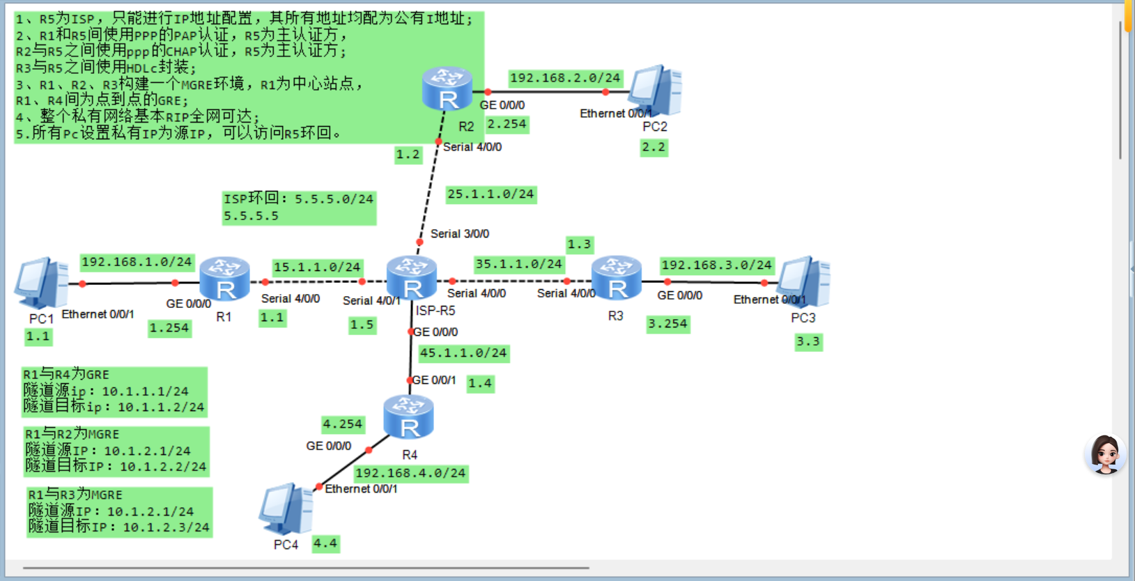
?1、R5為ISP,只能進行IP地址配置,其所有地址均配為公有I地址;
2、R1和R5間使用PPP的PAP認證,R5為主認證方,
R2與R5之間使用ppp的CHAP認證,R5為主認證方;
R3與R5之間使用HDLc封裝;
3、R1、R2、R3構建一個MGRE環境,R1為中心站點,
R1、R4間為點到點的GRE;
4、整個私有網絡基本RIP全網可達;
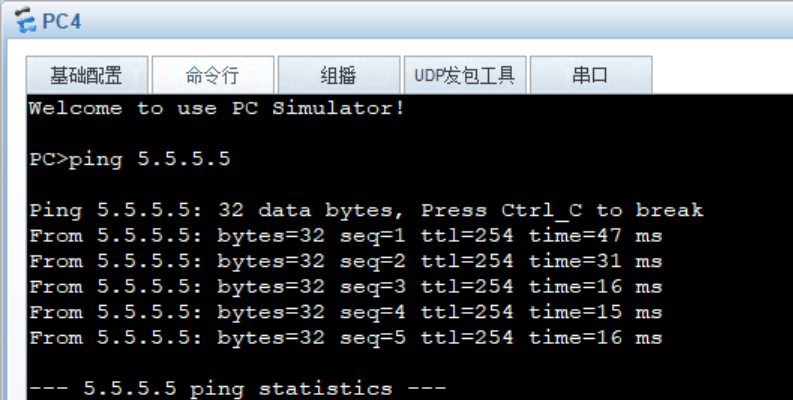
5.所有Pc設置私有IP為源IP,可以訪問R5環回。
三、分析
1、配置IP地址
2、配置靜態路由使得公網全網通。
3、配置PPP的PAP 認證,R5為主認證方。
步驟1:在R5上,開啟aaa模式,創建用戶名、密碼,設置權限
步驟2:在R5上,設置為PPP協議,進入物理接口設置PPP的認證模式為PAP
步驟3:在R1上,進入物理接口,配置相同的用戶名及密碼。
4、配置PPP的CHAP?認證,R5為主認證方。
步驟1:在R5上,開啟aaa模式,創建用戶名、密碼,設置權限
步驟2:在R5上,設置為PPP協議,進入物理接口設置PPP的認證模式為CHAP
步驟3:在R1上,進入物理接口,配置相同的用戶名及密碼。
5、配置HDLC封裝
兩邊都進入接口,修改接口類型為?hdlc
6、配置MGRE,R1為中心站點
步驟1:創建隧道接口,配置IP地址,封裝方式設置為MGRE(gre p2mp),配置隧道對應物理接口的源IP地址。
步驟2:在R1上配置中心站點,宣告NHRP域,在R2、R3上配置分支站點,并向中心站點注冊自身的隧道接口信息。
步驟3:配置RIP動態路由,宣告隧道網段和私網網段,使得可達全網可達。
7、配置GRE,R1為中心站點
步驟1:創建隧道接口,配置IP地址,封裝方式設置為GRE(gre),配置隧道對應物理接口的源IP地址和目標隧道封裝的物理接口的IP地址。
步驟2:配置RIP動態路由,宣告隧道網段和私網網段,使得可達全網可達。
8、配置EASY? IP使得所有PC都可訪問公網,訪問ISP的環回。
步驟1:配置缺省路由,全網可達,配置ACL,將私網的信息過濾抓包出來
步驟2:在接口下,同意放行ACL,私網PC可訪問公網ISP環回內容。
四、步驟
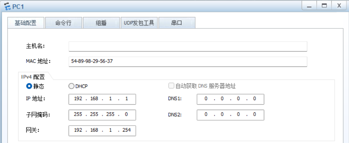
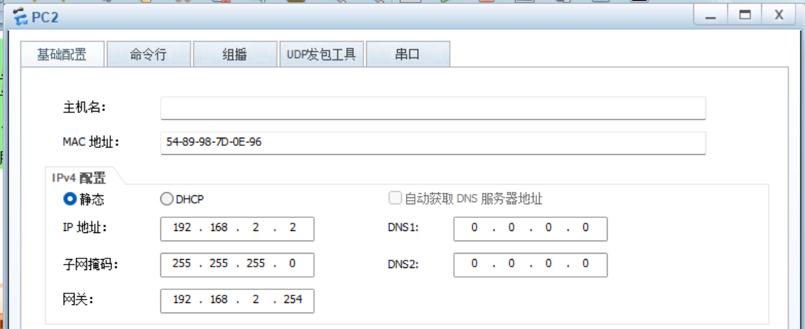
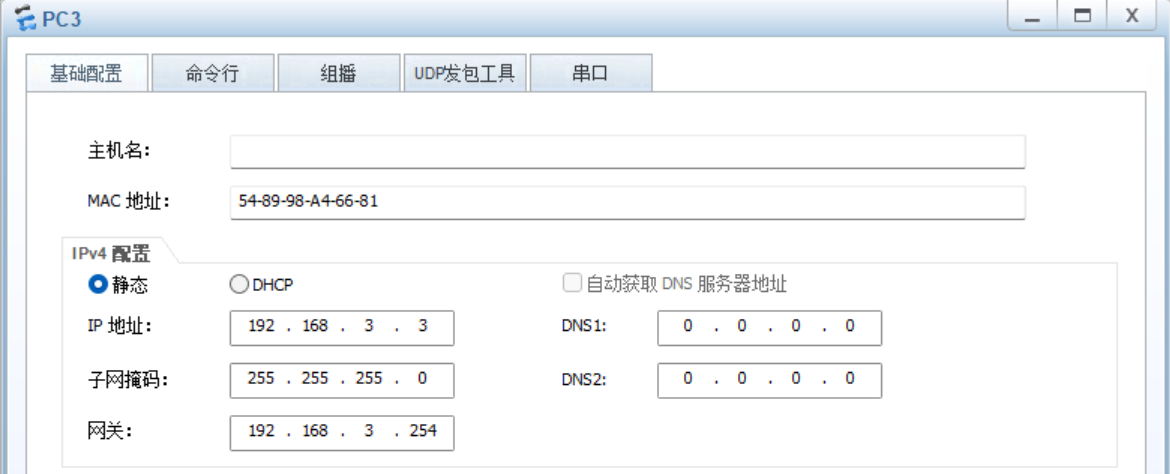
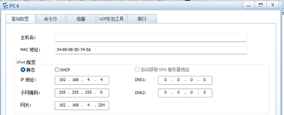
1、配置IP地址
PC:
 ?
?
路由器:
R1:
[R1]int g0/0/0
[R1-GigabitEthernet0/0/0]ip add 192.168.1.254 24
[R1-GigabitEthernet0/0/0]q
[R1]int Serial 4/0/0
[R1-Serial4/0/0]ip add 15.1.1.1 24
[R1-Serial4/0/0]q
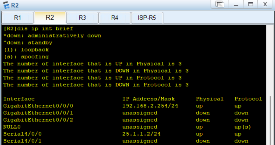
R2:
[R2]int g0/0/0
[R2-GigabitEthernet0/0/0]ip add 192.168.2.254 24
[R2-GigabitEthernet0/0/0]q
[R2]int Serial 4/0/0
[R2-Serial4/0/0]ip add 25.1.1.2 24
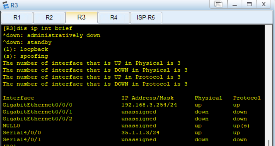
[R2-Serial4/0/0]qR3:
[R3]int g0/0/0
[R3-GigabitEthernet0/0/0]ip add 192.168.3.254 24
[R3-GigabitEthernet0/0/0]q
[R3]int Serial 4/0/0
[R3-Serial4/0/0]ip add 35.1.1.3 24
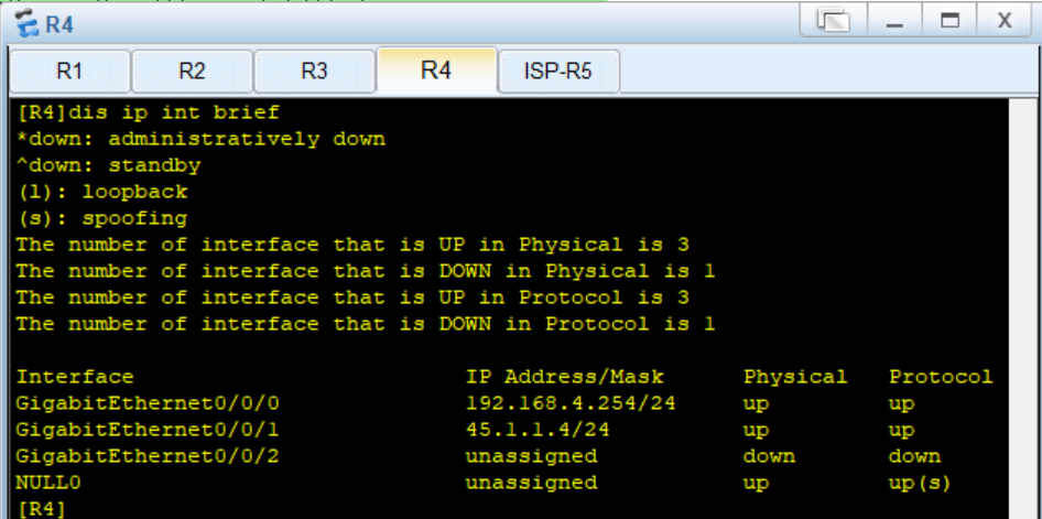
[R3-Serial4/0/0]qR4:
[R4]int g0/0/0
[R4-GigabitEthernet0/0/0]ip add 192.168.4.254 24
[R4-GigabitEthernet0/0/0]int g0/0/1
[R4-GigabitEthernet0/0/1]ip add 45.1.1.4 24
[R4-GigabitEthernet0/0/1]q
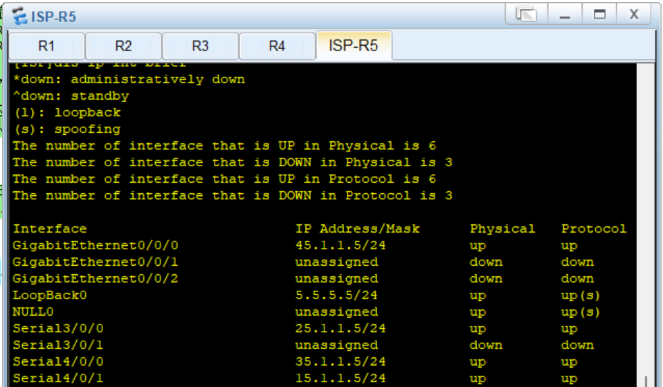
[R4]ISP:
[ISP]int g0/0/0
[ISP-GigabitEthernet0/0/0]ip add 45.1.1.5 24
[ISP-GigabitEthernet0/0/0]q
[ISP]int Serial 4/0/0
[ISP-Serial4/0/0]ip add 35.1.1.5 24
[ISP-Serial4/0/0]
[ISP-Serial4/0/0]int Serial 3/0/0
[ISP-Serial3/0/0]ip add 25.1.1.5 24
[ISP-Serial3/0/0]
[ISP-Serial3/0/0]int Serial 4/0/1
[ISP-Serial4/0/1]ip add 15.1.1.5 24
[ISP-Serial4/0/1]
[ISP-Serial4/0/1]q
[ISP]int l0
[ISP-LoopBack0]ip add 5.5.5.5 24
[ISP-LoopBack0]q
?配置結果:

 ?
?
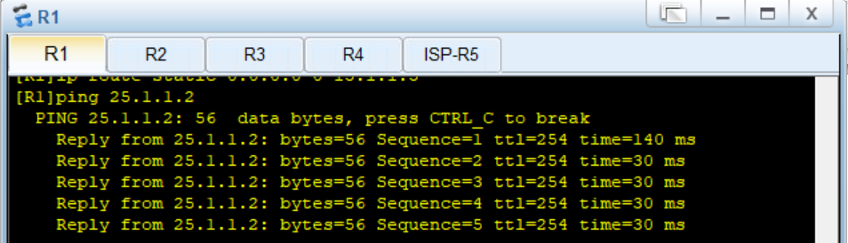
2、配置靜態路由,使得公網通。
[R1]ip route-static 0.0.0.0 0 15.1.1.5
[R2]ip route-static 0.0.0.0 0 25.1.1.5
[R3]ip route-static 0.0.0.0 0 35.1.1.5
[R4]ip route-static 0.0.0.0 0 45.1.1.5
測試:
 ?3、在R1、R5上配置PPP的PAP 認證,R5為主認證方。
?主認證方R5:在aaa模式下,創建用戶,說明協議為ppp協議,在接口下說明pap驗證。
[ISP]aaa
[ISP-aaa]local-user xixi password cipher xixi123 privilege level 15
Info: Add a new user.
[ISP-aaa]local-user xixi service-type ppp
[ISP-aaa]q
[ISP]int Serial 4/0/1
[ISP-Serial4/0/1]ppp authentication-mode pap
[ISP-Serial4/0/1]q
[ISP]
?被認證方R1:在接口下,配置相同的認證用戶名和密碼
[R1]int Serial 4/0/0
[R1-Serial4/0/0]ppp pa local-user xixi password cipher xixi123
?4、在R2、R5上配置PPP的CHAP認證,R5為主認證方
?主認證方R5:在aaa模式下,創建用戶,說明協議為ppp協議,在接口下說明chap驗證。
[ISP]aaa
[ISP-aaa]local-user haha password cipher haha123 privilege level 15
Info: Add a new user.
[ISP-aaa]local-user haha service-type ppp
[ISP-aaa]q
[ISP]int Serial 3/0/0
[ISP-Serial3/0/0]ppp authentication-mode chap
[ISP-Serial3/0/0]q
[ISP]
被認證方R2:在接口下,配置相同的認證用戶名和密碼
[R2]int Serial 4/0/0
[R2-Serial4/0/0]ppp chap user haha
[R2-Serial4/0/0]ppp chap password cipher haha123
[R2-Serial4/0/0]q
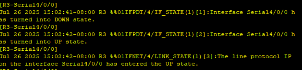
[R2]5、 在R3、R5上配置HDLC封裝
[ISP]int Serial 4/0/0
[ISP-Serial4/0/0]link-protocol hdlc
Warning: The encapsulation protocol of the link will be changed. Continue? [Y/N]
:y
[ISP-Serial4/0/0][R3]int Serial 4/0/0
[R3-Serial4/0/0]link-protocol hdlc
Warning: The encapsulation protocol of the link will be changed. Continue? [Y/N]
:y
[R3-Serial4/0/0]
?配置結果;
R3:
ISP:

?6、在R1~R3上配置MGRE,R1為中心站點
步驟1:創建隧道接口,配置IP地址,選擇封裝類型MGRP,配置源IP地址(隧道口對應的真實的物理口IP地址)
?R1:
[R1]int Tunnel 0/0/0
[R1-Tunnel0/0/0]ip add 10.1.2.1 24
[R1-Tunnel0/0/0]tunnel-protocol gre p2mp
[R1-Tunnel0/0/0]source 15.1.1.1
Jul 26 2025 15:10:12-08:00 R1 %%01IFNET/4/LINK_STATE(l)[0]:The line protocol IP
on the interface Tunnel0/0/0 has entered the UP state.
R2:
[R2]int Tunnel 0/0/0
[R2-Tunnel0/0/0]ip add 10.1.2.2 24
[R2-Tunnel0/0/0]tunnel-protocol gre p2mp
[R2-Tunnel0/0/0]source Serial 4/0/0
Jul 26 2025 15:15:31-08:00 R2 %%01IFNET/4/LINK_STATE(l)[0]:The line protocol IP
on the interface Tunnel0/0/0 has entered the UP state.
[R2-Tunnel0/0/0]
R3:
[R3]int Tunnel 0/0/0
[R3-Tunnel0/0/0]ip add 10.1.2.3 24
[R3-Tunnel0/0/0]tunnel-protocol gre p2mp
[R3-Tunnel0/0/0]source Serial 4/0/0
Jul 26 2025 15:17:30-08:00 R3 %%01IFNET/4/LINK_STATE(l)[0]:The line protocol IP
on the interface Tunnel0/0/0 has entered the UP state.
[R3-Tunnel0/0/0]
步驟2:配置nhrp域,在R2、R3上將自身信息注冊到中心站點R1上(中心隧道IP地址,中心隧道對應的物理口IP地址)
[R1-Tunnel0/0/0]nhrp network-id 100[R2-Tunnel0/0/0]nhrp network-id 100
[R2-Tunnel0/0/0]nhrp entry 10.1.2.1 15.1.1.1 register[R3-Tunnel0/0/0]nhrp network-id 100
[R3-Tunnel0/0/0]nhrp entry 10.1.2.1 15.1.1.1 register
查看配置結果:
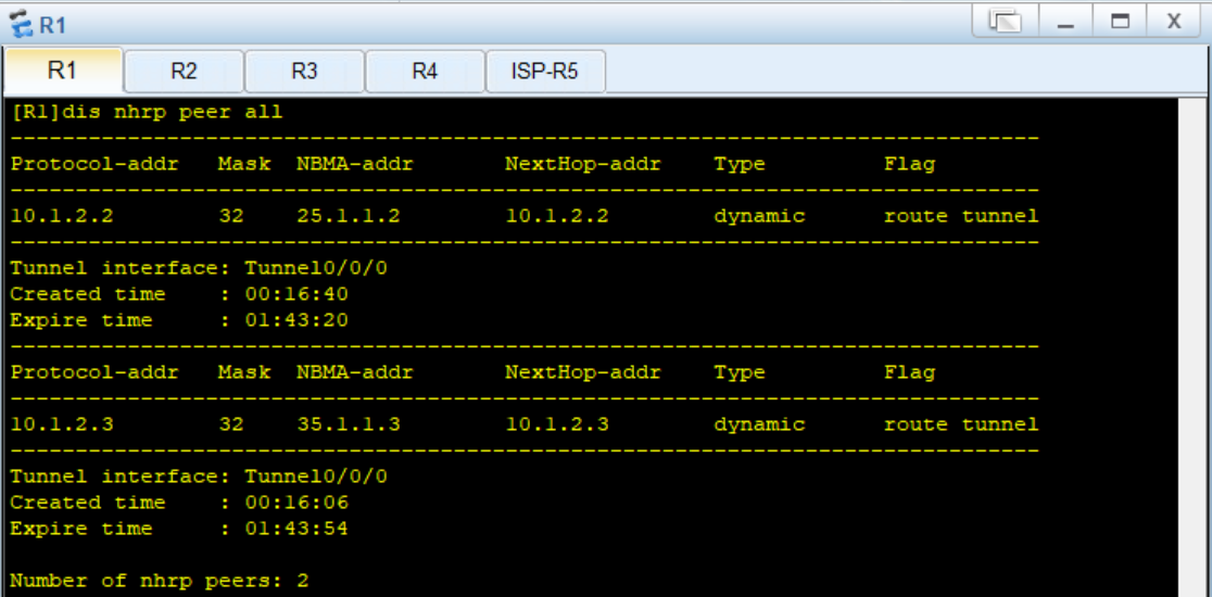
測試:
步驟3:配置RIP,選擇v2版本,關閉自動匯總,宣告網段(主網段,不是子網段)
?R1:
[R1]rip 1
[R1-rip-1]version 2
[R1-rip-1]network 192.168.1.0
[R1-rip-1]undo summary
[R1-rip-1]network 10.0.0.0
R2:
[R2]rip 1
[R2-rip-1]version 2
[R2-rip-1]undo summary
[R2-rip-1]network 192.168.2.0
[R2-rip-1]network 10.0.0.0
[R2-rip-1]
R3:
[R3]rip 1
[R3-rip-1]v 2
[R3-rip-1]undo summary
[R3-rip-1]network 192.168.3.0
[R3-rip-1]network 10.0.0.0
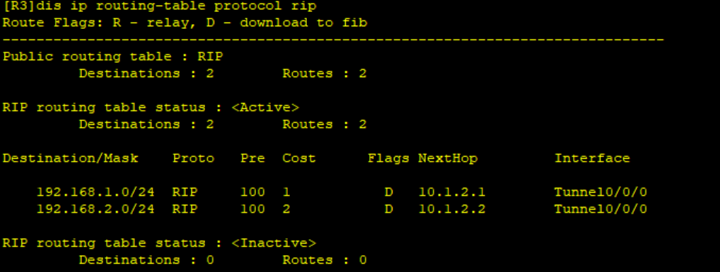
[R3-rip-1]?查詢RIP配置結果:
R1
R2
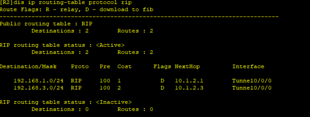
R3:
?
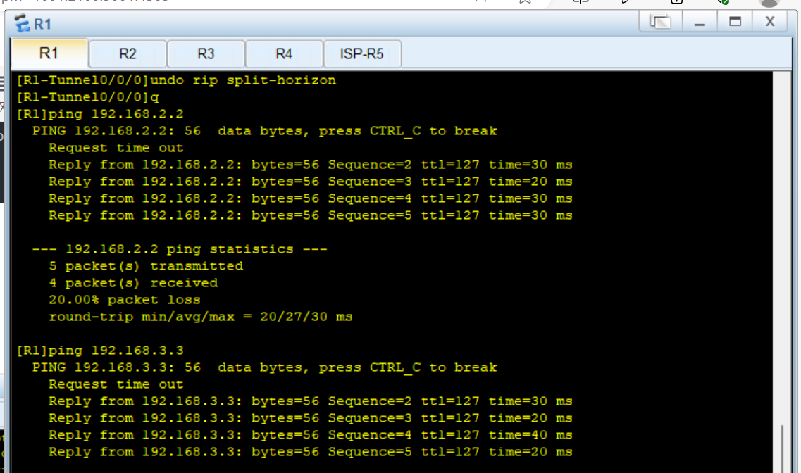
在R1接口上關閉RIP水平分割,在中心上開啟偽廣播。
[R1]int Tunnel 0/0/0
[R1-Tunnel0/0/0]nhrp entry multicast dynamic
[R1-Tunnel0/0/0]undo rip split-horizon
[R1-Tunnel0/0/0]q
[R1]
R2、R3上關閉RIP水平分割
[R2-Tunnel0/0/0]undo rip split-horizon
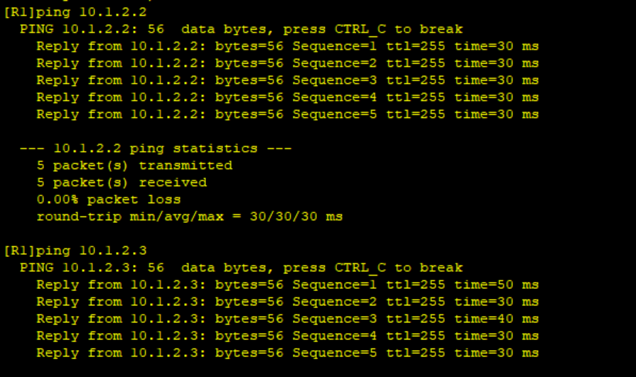
[R3-Tunnel0/0/0]undo rip split-horizon測試R1~R3可達
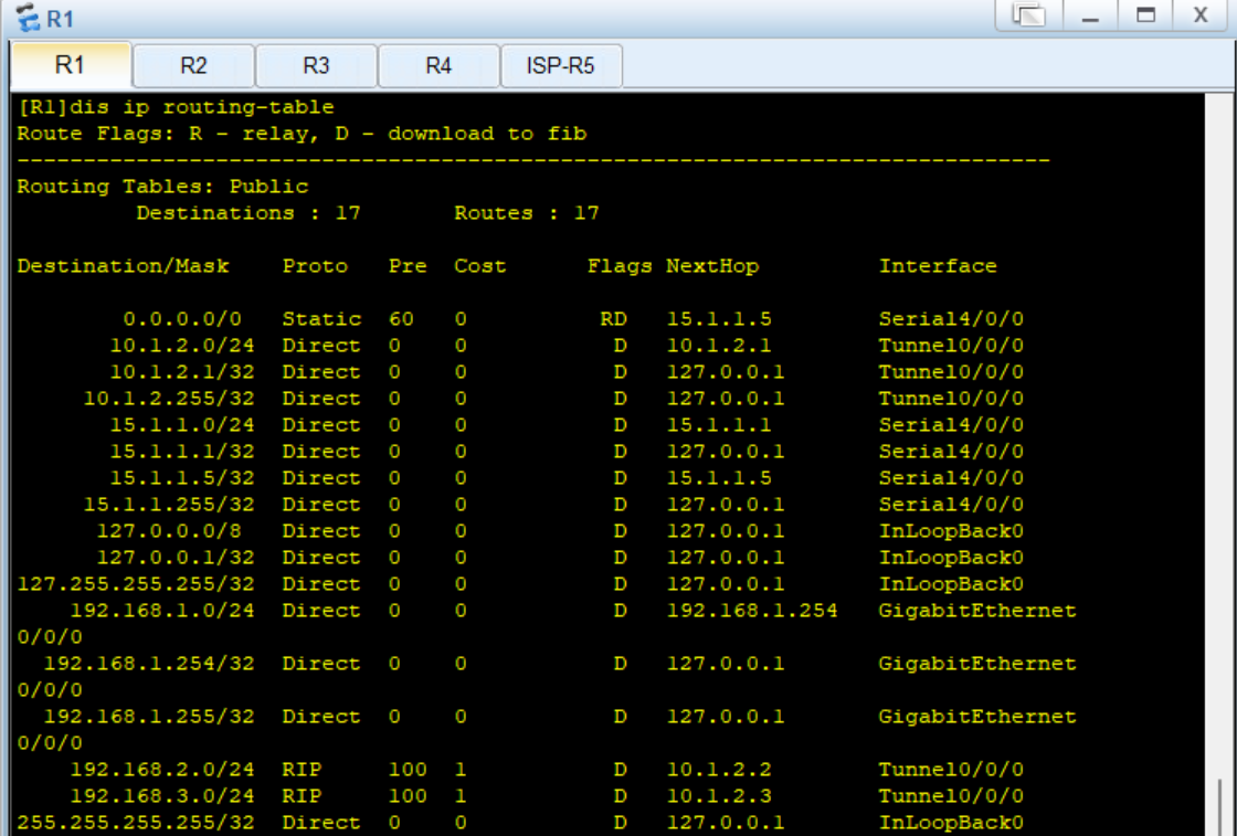
?
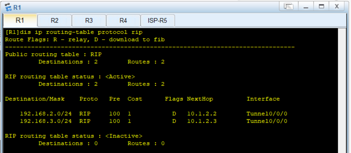
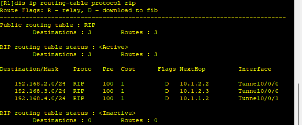
?關閉RIP水平分割后R1路由表信息:
?7、配置GRE,R1為中心站點
步驟1:創建隧道接口,配置IP地址,選擇封裝類型GRP,配置源目IP地址(隧道口對應的真實的物理口IP地址)
R1:
[R1]int Tunnel 0/0/1
[R1-Tunnel0/0/1]ip add 10.1.1.1 24
[R1-Tunnel0/0/1]tunnel-protocol gre
[R1-Tunnel0/0/1]source 15.1.1.1
[R1-Tunnel0/0/1]destination 45.1.1.4
Jul 26 2025 16:12:31-08:00 R1 %%01IFNET/4/LINK_STATE(l)[0]:The line protocol IP
on the interface Tunnel0/0/1 has entered the UP state.
[R1-Tunnel0/0/1]
R4:
[R4]int Tunnel 0/0/1
[R4-Tunnel0/0/1]ip add 10.1.1.2 24
[R4-Tunnel0/0/1]tunnel-protocol gre
[R4-Tunnel0/0/1]source 45.1.1.4
[R4-Tunnel0/0/1]destination 15.1.1.1
Jul 26 2025 16:19:27-08:00 R4 %%01IFNET/4/LINK_STATE(l)[0]:The line protocol IP
on the interface Tunnel0/0/1 has entered the UP state.
[R4-Tunnel0/0/1]
測試配置:
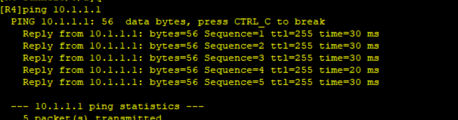
步驟2:配置RIP,選擇v2版本,關閉自動匯總,宣告網段(主網段,不是子網段)
R1配置MGRE時已經配置了RIP。
R4:
[R4]rip 1
[R4-rip-1]v 2
[R4-rip-1]undo summary
[R4-rip-1]network 192.168.4.0
[R4-rip-1]network 10.0.0.0
[R4-rip-1]
?配置結果:
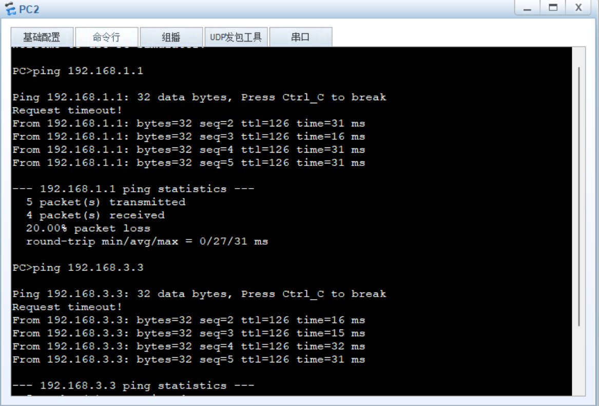
 ?9、配置EASY IP ,使得PC可以訪問公網ISP的環回
步驟1:配置ACL
公網已全網可達。
[R1]acl 2000
[R1-acl-basic-2000]rule permit source 192.168.1.0 0.0.0.255[R2]acl 2000
[R2-acl-basic-2000]rule permit source 192.168.2.0 0.0.0.255[R3]acl 2000
[R3-acl-basic-2000]rule permit source 192.168.3.0 0.0.0.255[R4]acl 2000
[R4-acl-basic-2000]rule permit source 192.168.4.0 0.0.0.255
?步驟2:在接口nat下發ACL
[R1]int Serial 4/0/0
[R1-Serial4/0/0]nat outbound 2000[R2]int Serial 4/0/0
[R2-Serial4/0/0]nat outbound 2000[R3]int Serial 4/0/0
[R3-Serial4/0/0]nat outbound 2000[R4]int g0/0/1
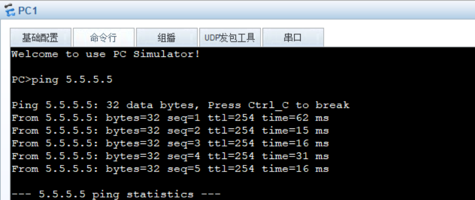
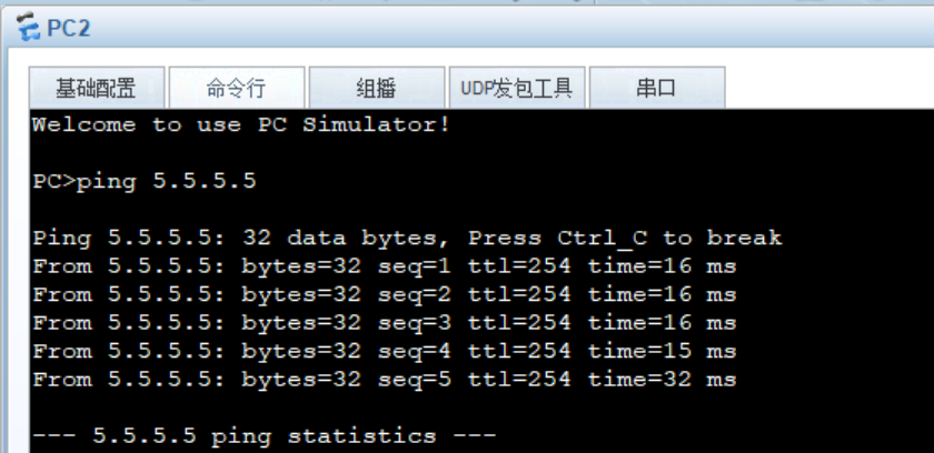
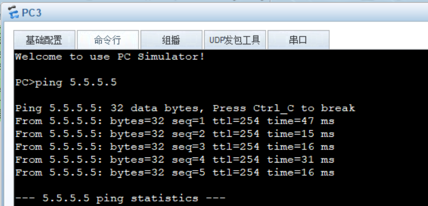
[R4-GigabitEthernet0/0/1]nat outbound 2000測試:
?
?
 ?
?
?


)
---從DeepseekR1-1.5B到Qwen-2.5-1.5B蒸餾)

)
)


)


)


)
)
