一、? ? ? ? linux I2C體系結構
? ? ? ? linux的I2C體系結構分為3個組成部分
? ? ? ? 1)I2C核心
? ? ? ? I2C核心提供了I2C總線驅動與設備驅動的注冊、注銷方法,I2C通信方法(即Algorithm)上層的與具體適配器無關的代碼及其探測設備、檢測設備地址的上層代碼等,如圖:
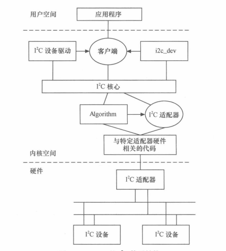
? ? ? ? 2)I2C總線驅動
? ? ? ? I2C總線驅動是對I2C硬件體系結構中適配器端的實現,適配器可由CPU控制,甚至可以直接集成在CPU內部。
? ? ? ? I2C總線驅動?主要包含I2C適配器數據結構I2C_adaper、I2C適配器的Algorithm數據結構I2C_algorithm和控制I2C適配器產生通信信號的函數。經I2C總線驅動的代碼,我們可以控制I2C適配器以主控方式產生開始位、停止位、讀寫周期,以及以從設備方式被讀寫、產生ACK等。
? ? ? ? 3)I2C設備驅動
? ? ? ? I2C設備驅動(也稱客戶驅動)是對I2C硬件體系結構設備端的實現,設備一般掛接在受CPU控制的I2C的適配器上,通過I2C適配器與CPU交換數據。
? ? ? ? I2C設備驅動主要包含數據結構I2c_driver和i2c_client,我們需要根據具體設備實現其中的成員函數。
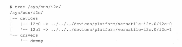
? ? ? ? 在linux kernel中,所有的i2c設備都在sysfs文件系統中顯示,存于/sys/bus/i2c/目錄下,以適配器地址和芯片的地址的形式列出,例如:
????????
? ? ? ? 在linux內核源碼中的drivers目錄下有一個i2c目錄,而在I2C目錄下包含如下文件和文件夾
? ? ? ? 1)i2c-core.c
? ? ? ? 這個文件實現了i2C核心的功能以及/proc/bus/i2c*接口?。
? ? ? ? 2)i2c-dev.c
? ? ? ? 實現了I2c適配器設備文件的功能,每個I2c適配器都被分配一個設備。通過適配器訪問設備時的主設備號都為89,次設備號為0-255。應用程序通過“i2c-%d”(i2c-0,i2c-1,...,i2c-10,...)文件名并使用文件操作接口open()、write()、read()、ioctl()、和close()等來訪問這個設備。
? ? ? ? i2c-dev.c并不是針對特定都設備而設計都,只是提供了通用都read()、write()和ioctl()等接口,應用層可以借用這些接口訪問掛接在適配器上的i2c設備的存儲空間或寄存器,并控制i2c設備的工作方式。
? ? ? ? 3)busses文件夾
? ? ? ? 這個文件包含了一些I2c主機控制權的驅動,如i2c-tegra.c、i2c-omap.c、i2c-versatile.c、i2c-s3c2410.c等
? ? ? ? 4)algos文件夾
? ? ? ? 實現了一些i2c總線適配器的通信方法
? ? ? ? 此外,內核中i2c.h文件對i2c_adapter、i2c_algorithm、i2c_driver和i2c_client這4個數據結構進行了定義。理解這四個結構體的作用十分重要,他們的定義位于include/linux/i2c.h文件中
719 struct i2c_adapter {720 struct module *owner;721 unsigned int class; /* classes to allow probing for */722 const struct i2c_algorithm *algo; /* the algorithm to access the bus */723 void *algo_data;724 725 /* data fields that are valid for all devices */726 const struct i2c_lock_operations *lock_ops;727 struct rt_mutex bus_lock;728 struct rt_mutex mux_lock;729 730 int timeout; /* in jiffies */731 int retries;732 struct device dev; /* the adapter device */733 unsigned long locked_flags; /* owned by the I2C core */734 #define I2C_ALF_IS_SUSPENDED 0735 #define I2C_ALF_SUSPEND_REPORTED 1736 737 int nr;738 char name[48];739 struct completion dev_released;740 741 struct mutex userspace_clients_lock;742 struct list_head userspace_clients;743 744 struct i2c_bus_recovery_info *bus_recovery_info;745 const struct i2c_adapter_quirks *quirks;746 747 struct irq_domain *host_notify_domain;748 struct regulator *bus_regulator;749 };
541 struct i2c_algorithm {542 /*543 * If an adapter algorithm can't do I2C-level access, set master_xfer544 * to NULL. If an adapter algorithm can do SMBus access, set545 * smbus_xfer. If set to NULL, the SMBus protocol is simulated546 * using common I2C messages.547 *548 * master_xfer should return the number of messages successfully549 * processed, or a negative value on error550 */551 int (*master_xfer)(struct i2c_adapter *adap, struct i2c_msg *msgs,552 int num);553 int (*master_xfer_atomic)(struct i2c_adapter *adap,554 struct i2c_msg *msgs, int num);555 int (*smbus_xfer)(struct i2c_adapter *adap, u16 addr,556 unsigned short flags, char read_write,557 u8 command, int size, union i2c_smbus_data *data);558 int (*smbus_xfer_atomic)(struct i2c_adapter *adap, u16 addr,559 unsigned short flags, char read_write,560 u8 command, int size, union i2c_smbus_data *data);561 562 /* To determine what the adapter supports */563 u32 (*functionality)(struct i2c_adapter *adap);564 565 #if IS_ENABLED(CONFIG_I2C_SLAVE)566 int (*reg_slave)(struct i2c_client *client);567 int (*unreg_slave)(struct i2c_client *client);568 #endif569 };? ? ? ? 上述代碼551行master_xfer對應為I2c傳輸函數指針,i2c主機驅動的大部分工作也聚集在這里。上述第555行代碼對應為SMbus傳輸函數指針,SMbus不需要增加額外引腳,與i2c總線相比,在訪問時序上也有一定的差異。?
271 struct i2c_driver {272 unsigned int class;273 274 /* Standard driver model interfaces */275 int (*probe)(struct i2c_client *client);276 void (*remove)(struct i2c_client *client);277 278 279 /* driver model interfaces that don't relate to enumeration */280 void (*shutdown)(struct i2c_client *client);281 282 /* Alert callback, for example for the SMBus alert protocol.283 * The format and meaning of the data value depends on the protocol.284 * For the SMBus alert protocol, there is a single bit of data passed285 * as the alert response's low bit ("event flag").286 * For the SMBus Host Notify protocol, the data corresponds to the287 * 16-bit payload data reported by the slave device acting as master.288 */289 void (*alert)(struct i2c_client *client, enum i2c_alert_protocol protocol,290 unsigned int data);291 292 /* a ioctl like command that can be used to perform specific functions293 * with the device.294 */295 int (*command)(struct i2c_client *client, unsigned int cmd, void *arg);296 297 struct device_driver driver;298 const struct i2c_device_id *id_table;299 300 /* Device detection callback for automatic device creation */301 int (*detect)(struct i2c_client *client, struct i2c_board_info *info);302 const unsigned short *address_list;303 struct list_head clients;304 305 u32 flags;306 };
330 struct i2c_client {331 unsigned short flags; /* div., see below */332 #define I2C_CLIENT_PEC 0x04 /* Use Packet Error Checking */333 #define I2C_CLIENT_TEN 0x10 /* we have a ten bit chip address */334 /* Must equal I2C_M_TEN below */335 #define I2C_CLIENT_SLAVE 0x20 /* we are the slave */336 #define I2C_CLIENT_HOST_NOTIFY 0x40 /* We want to use I2C host notify */337 #define I2C_CLIENT_WAKE 0x80 /* for board_info; true iff can wake */338 #define I2C_CLIENT_SCCB 0x9000 /* Use Omnivision SCCB protocol */339 /* Must match I2C_M_STOP|IGNORE_NAK */340 341 unsigned short addr; /* chip address - NOTE: 7bit */342 /* addresses are stored in the */343 /* _LOWER_ 7 bits */344 char name[I2C_NAME_SIZE];345 struct i2c_adapter *adapter; /* the adapter we sit on */346 struct device dev; /* the device structure */347 int init_irq; /* irq set at initialization */348 int irq; /* irq issued by device */349 struct list_head detected;350 #if IS_ENABLED(CONFIG_I2C_SLAVE)351 i2c_slave_cb_t slave_cb; /* callback for slave mode */352 #endif353 void *devres_group_id; /* ID of probe devres group */354 };? ? ? ? 下面分析這4個數據結構的作用及盤根錯節的關系
? ? ? ? 1)?i2c_adapter(適配器)與i2_algorithm(算法,通信方法)
? ? ? ? i2c_adapter對應于物理上的一個適配器,而i2c_algorithm對應一套通信方法。一個i2c適配器需要i2c_algorithm提供的通信函數來控制適配器產生特定的訪問周期。缺少i2c_algorithm的i2c_adapter什么也做不了,因此i2c_adapter中包含所使用的i2c_algorithm的指針。
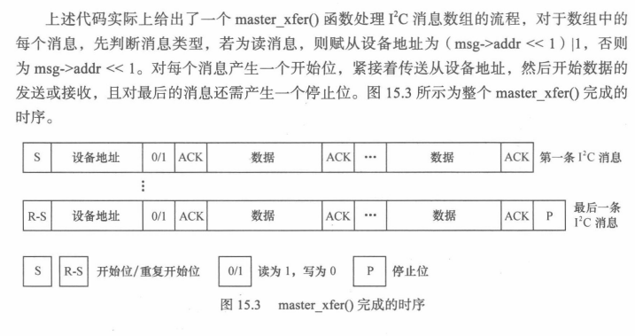
? ? ? ? i2c_algorithm的關鍵函數master_xfer()用于產生訪問周期需要的信號,以i2c_msg(即i2c信息)為單位。i2c_msg結構體也是非常重要的,它定義于include/uapi/linux/i2c.h(在uapi目錄下,證明用戶空間的應用也可能用這個結構體)中,下圖給出了它的定義,其中的成員表明了i2c的傳輸地址、方向、緩沖區、緩沖區長度等信息。
73 struct i2c_msg {74 __u16 addr;75 __u16 flags;76 #define I2C_M_RD 0x0001 /* guaranteed to be 0x0001! */77 #define I2C_M_TEN 0x0010 /* use only if I2C_FUNC_10BIT_ADDR */78 #define I2C_M_DMA_SAFE 0x0200 /* use only in kernel space */79 #define I2C_M_RECV_LEN 0x0400 /* use only if I2C_FUNC_SMBUS_READ_BLOCK_DATA */80 #define I2C_M_NO_RD_ACK 0x0800 /* use only if I2C_FUNC_PROTOCOL_MANGLING */81 #define I2C_M_IGNORE_NAK 0x1000 /* use only if I2C_FUNC_PROTOCOL_MANGLING */82 #define I2C_M_REV_DIR_ADDR 0x2000 /* use only if I2C_FUNC_PROTOCOL_MANGLING */83 #define I2C_M_NOSTART 0x4000 /* use only if I2C_FUNC_NOSTART */84 #define I2C_M_STOP 0x8000 /* use only if I2C_FUNC_PROTOCOL_MANGLING */85 __u16 len;86 __u8 *buf;87 };? ? ? ? 2)i2c_driver與i2c_client
? ? ? ? i2c_driver對應于一套驅動方法,其主要成員函數是probe()、remove()、suspen()、resumu()等,另外,struct i2c_device_id形式的id_table是該驅動所支持的i2c設備的ID表。i2c_client對應于真實的物理設備,每個i2c設備都需要一個i2c_client來描述。i2c_driver與i2c_client的關系是一對多,一個i2c_driver可以支持多個同類型的i2c_clinet?。
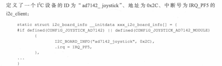
? ? ? ? i2c_client的信息通常在BSP的板文件中通過i2c_board_info填充,如下:
? ? ? ? 在i2c總線驅動i2c_bus_type的match()函數i2c_device_match()中,會調用i2c_match_id()函數匹配在板文件中定義的ID和i2c_driver所支持的ID表 。??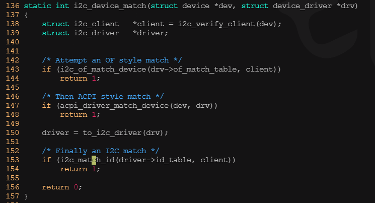
? ? ? ? 3)i2c_adapter與i2c_client
? ? ? ? i2c_adapter與i2c_cilent的關系與i2c硬件體系中適配器和設備的關系一致,即i2c_clinet依附于i2c_adapter。由于一個適配器可以連接多個i2c設備,所有一個i2c_adapter也可以被多個i2c_client依附,i2c_adapter中包含依附它的i2c_client的鏈表。
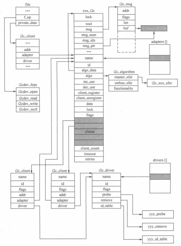
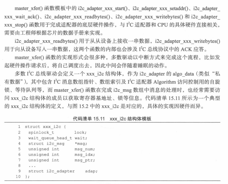
? ? ? ?假設i2c總線適配器xxx上有兩個使用相同驅動程序的yyyI2c設備,在打開該I2c總線的設備節點后,相關數據結構之間的邏輯組織關系如圖:
? ? ? ?
? ? ? ? ?從上面的分析可知,雖然i2c硬件體系結構比較簡單,但是i2c體系結構在linux中的實現卻相當復雜。當工程師拿到實際的電路板時 ,面對復雜的linux i2c子系統,應該如何下手寫驅動呢?究竟有哪些是需要親自做的,哪些是內核已經提供的呢?理清這個問題非常有意義,可以使我們做面對具體問題時迅速抓住重點。
? ? ? ? 一方面,適配器驅動可能是linux內核本身還不包含的;另一方面,掛接做適配器上的具體設備驅動可能也是linux內核還不包含的。因此,工程師要實現的主要工作如下:
? ? ? ? 1)提供I2c硬件適配器的硬件驅動,探測、初始化i2c適配器(如申請i2c的i/O地址和中斷號)、驅動cpu控制的i2c適配器從硬件上產生各種信號以及處理i2c中斷等。
? ? ? ? 2)提供i2c適配器的Algorithm,用具體適配器的xxx_xfer()函數填充i2c_algorithm的master_xfer指針,并把i2c_algorithm指針賦值給i2c_adapter的algo指針。
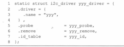
? ? ? ? 3)實現i2c設備驅動中的i2c_driver接口,具體設備yyy的yyy_probe()、yyy_remove()、yyy_suspen()、yyy_resume()函數指針和i2c_device_id設備ID表賦值給i2c_driver的probe、remove、suspend、resume和id_table指針。
? ? ? ? 4)實現i2c設備所對應類型的具體驅動,i2c_driver只是實現設備與總線的掛接,而掛接在總線上的設備則千差萬別。例如,如果是字符設備,就實現文件操作接口,即實現具體設備yyy的yyy_read()、yyy_write()和yyy_ioctl函數等;如果是聲卡就實現ALSA驅動。
? ? ? ? 上述工作中前兩個屬于I2c總線驅動,后兩個屬于i2c設備驅動。
二、? ? ? ? linux I2c核心?
? ? ? ? I2c核心(drivers/i2c/i2c-core-base.c)?中提供了一組不依賴于硬件平臺的接口函數,這個文件一般不需要被工程師修改,但是理解其中的主要函數非常關鍵,因為i2c總線驅動和設備驅動以i2c核心作為紐帶。i2c核心的主要函數如下。
? ? ? ? 1)增加、刪除i2c_adapter
????????
? ? ?
?
? ? ? ? 2)增加/刪除i2c_dirver
?????????
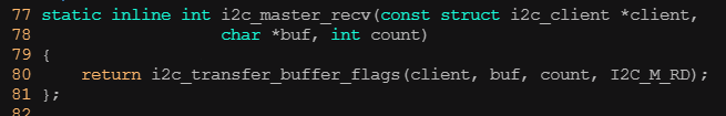
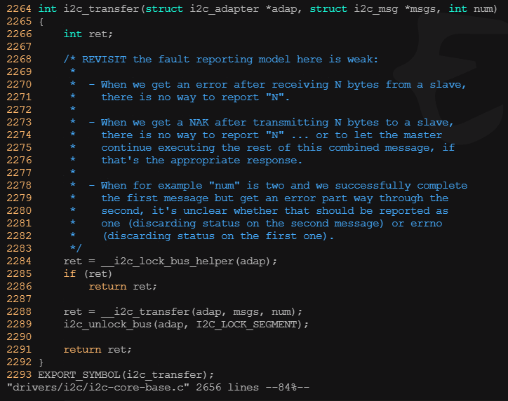
? ? ? ? 3)i2c傳輸、發送和接收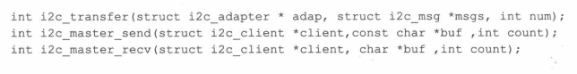
? ? ? ? i2c_transfer()函數用于進行i2c適配器和i2c設備之間的一組消息交互,其中第2個參數是指向i2c_msg數組的指針,所以i2c_transfer()一次可以傳輸多個i2c_msg(考慮到很多外設的讀寫波形比較復雜,比如讀寄存器可能要先寫,所以需要兩個以上的消息)。而對于時序比較簡單的外設,i2c_maste_send()函數和i2c_master_recv()函數內部都會調用i2c_transfer()函數分別完成一條寫消息和讀消息。
??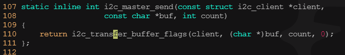
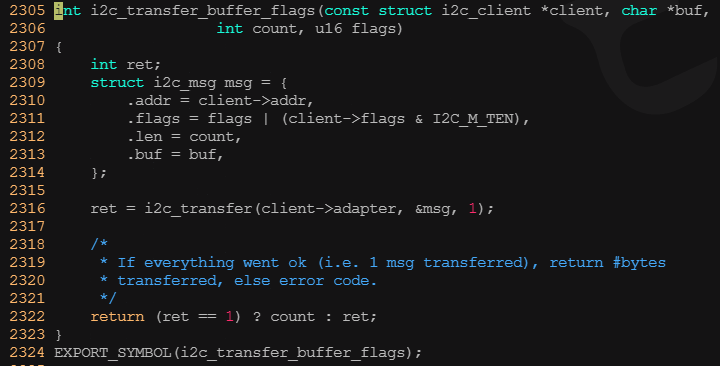
? ? ? ? i2c_transfer()函數本身不具備驅動適配器物理硬件以完成消息交互的能力,它只是尋找到與i2c_adapter對應的i2c_algorithm,并使用i2c_algorithm的master_xfer()函數真正驅動硬件流程。
三、? ? ? ? linux I2c適配器驅動
? ? ? ? 3.1?????????I2c適配器驅動的注冊與注銷
? ? ? ? 由于I2c總線控制器通常是在內存上的,所以本身也連接在platform總線上,要通過platform_driver和platform_device的匹配來執行。因此盡管i2c適配器給別人提供了總線,它自己也被認為是接在platform總線上的一個客戶。linux的總線、設備和驅動模型實際上是一個樹形結構,每個節點雖然可能成為別人的總線控制器,但是自己也被認為是從上一級總線枚舉出來的。
? ? ? ? 通常我們會在與I2c適配器所對應的platform_driver的probe()函數中完成兩個工作。
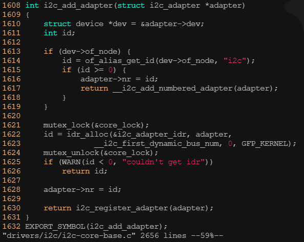
? ? ? ? 1)初始化I2c適配器所使用的硬件資源,如申請I/O地址、中斷號、時鐘等
? ? ? ? 2)???通過i2c_add_adapter()添加i2c_adapter的數據結構,當然這個i2c_adapter數據結構的成員已經被xxx適配器的相應函數指針初始化。
? ? ? ? 通常我們會在platform_driver的remove()函數中完成與加載函數相反的工作
? ? ? ? 3)釋放i2c適配器所使用的硬件資源,如釋放I/O地址、中斷號、時鐘等。
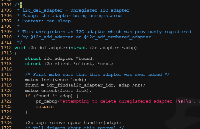
? ? ? ? 4)通過i2c_del_adapter()刪除i2c_adapter的數據結構
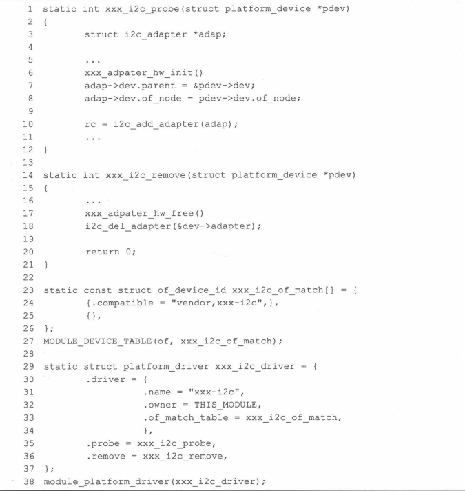
? ? ? ? 上訴代碼中的xxx_adpater_hw_init()和xxx_adpater_hw_free()函數的實現都與具體的CPU和i2c適配硬件直接相關。
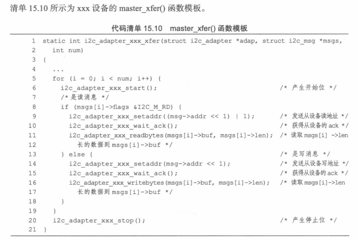
? ? ? ? 3.2? ? ? ? I2c總線的通信方法?
? ? ? ? 我們需要為特定的i2c適配器實現通信方法,主要是實現i2c_algorithm的functionality()函數和master_xfer()函數。
? ? ? ? functionality()函數非常,用于返回algorithm所支持的通信協議,如I2C_FUNC_I2C、I2C_FUNC_10BIT_ADDR、I2C_FUNC_SMBUS_READ_BYTE、I2C_FUNC_SMBUS_WRITE_BYTE等。
? ? ? ? master_xfer()函數在i2c適配器上完成傳遞給它的i2c_msg數組中的每個I2C消息。
?
 四、? ? ? ? linux I2c設備驅動?
? ? ? ? ?I2c設備驅動要使用i2c_driver和i2c_client數據結構并填充i2c_driver中的成員函數。i2c_client一般被包含在設備的私有信息結構體yyy_data中,而i2c_driver則適合被定義為全局變量并初始化。
????????
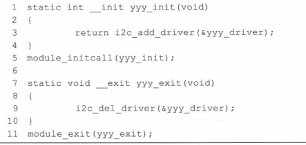
? ? ? ? 4.1? ? ? ? linux I2c設備驅動的模塊加載與卸載
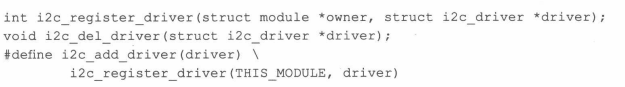
? ? ? ? i2c設備驅動的模塊加載函數通過i2c核心的i2c_add_driver()API函數添加i2c_driver的工作,而模塊卸載函數需要做相反的工作:通過i2c核心的i2c_del_driver()函數刪除i2c_dirver 。模板如下:
????????
????????4.2、? ? ? ? linux I2c設備驅動的數據傳輸?
? ? ? ? 在i2c設備上讀寫數據的時序且數據通常通過i2c_msg數組進行組織,最后通過i2c_transfer()函數完成。?
????????
? ? ? ? 4.3、 linux的i2c-dev.c文件分析
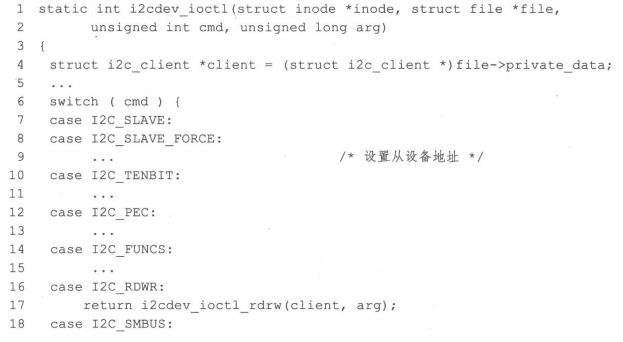
?????????i2c-dev.c完全可以被看作一個i2c設備驅動,不過,它實現的i2c-client是虛擬的,臨時的。主要是為了方便從用戶空間操作i2c外設。i2c-dev.c針對每個i2c適配器生成一個主設備號為89的設備文件,實現了i2c_driver的成員函數及其文件操作接口,因此i2c-dev.c的主體是“i2c_driver成員函數+字符設備驅動”。
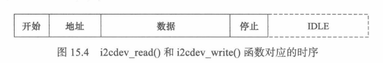
? ? ? ? i2c-dev.c提供的i2cdev_read()、i2cdec_write()函數對應于用戶空間要使用的read()和write()文件操作接口,這兩個函數分別調用i2c核心的i2c_maser_recv()和i2c_master_send()函數來構造一條i2c消息并引發適配器Algorithm通信函數的調用,以完成消息的傳輸,它對應下面的時序:
????????
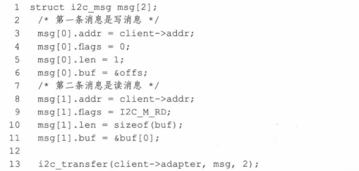
? ? ? ? 但是,很遺憾,大多數稍微復雜一點的i2c設備的讀寫流程并不對應一條消息,往往需要兩條甚至多條消息來進行一次讀寫周期(即下面圖示模式),在這種情況下,在應用層仍然調用read()、write()文件API來讀寫I2c設備,將不能正確地讀寫。
????????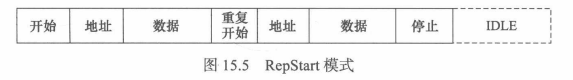
? ? ? ? 鑒于以上原因,i2c-dev.c中i2cdev_read()和i2cdec_write()函數不具備太強的通用性,沒有太大的實用價值,只能適用非RepStart模式的情況。對于由兩條以上消息組成的讀寫?,在用戶空間需要組織i2c_msg消息數組并調用I2C_RDWR IOCTL命令。
????????
????????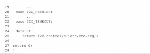 ?
?
? ? ? ? 常用的IOCTL包括I2C_SLAVE(設置從設備地址)、I2C_RETRIES(沒有收到設備ACK情況下的重試次數,默認為1)、I2C_TIMEOU(超時)以及I2C_RDWR。
五、Tegra I2c總線驅動實例
? ? ? ? NVIDIA Tegra I2c總線總線驅動位于drivers/i2c/busses/i2c-tegra.c文件中,這里不具體研究它的硬件細節,只看一下驅動框架和流程。
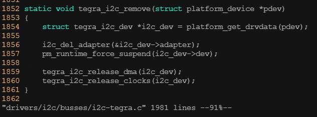
? ? ? ? I2c總線驅動是一個單獨的驅動,在模塊的加載和卸載函數中,只需要注冊和注銷platform_driver結構體。
1629 static const struct of_device_id tegra_i2c_of_match[] = {
1630     { .compatible = "nvidia,tegra194-i2c", .data = &tegra194_i2c_hw, },
1631     { .compatible = "nvidia,tegra186-i2c", .data = &tegra186_i2c_hw, },
1632 #if IS_ENABLED(CONFIG_ARCH_TEGRA_210_SOC)
1633     { .compatible = "nvidia,tegra210-i2c-vi", .data = &tegra210_i2c_hw, },
1634 #endif
1635     { .compatible = "nvidia,tegra210-i2c", .data = &tegra210_i2c_hw, },
1636     { .compatible = "nvidia,tegra124-i2c", .data = &tegra124_i2c_hw, },
1637     { .compatible = "nvidia,tegra114-i2c", .data = &tegra114_i2c_hw, },
1638     { .compatible = "nvidia,tegra30-i2c", .data = &tegra30_i2c_hw, },
1639     { .compatible = "nvidia,tegra20-i2c", .data = &tegra20_i2c_hw, },
1640 #if IS_ENABLED(CONFIG_ARCH_TEGRA_2x_SOC)
1641     { .compatible = "nvidia,tegra20-i2c-dvc", .data = &tegra20_i2c_hw, },
1642 #endif
1643     {},
1644 };
1645 MODULE_DEVICE_TABLE(of, tegra_i2c_of_match);1967 static struct platform_driver tegra_i2c_driver = {
1968     .probe = tegra_i2c_probe,
1969     .remove_new = tegra_i2c_remove,
1970     .driver = {
1971         .name = "tegra-i2c",
1972         .of_match_table = tegra_i2c_of_match,
1973         .acpi_match_table = tegra_i2c_acpi_match,
1974         .pm = &tegra_i2c_pm,
1975     },
1976 };
1977 module_platform_driver(tegra_i2c_driver);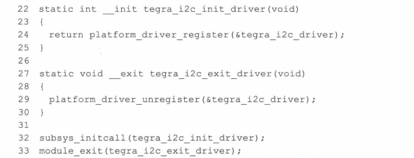
? ? ? ? 當在arch/arm/mach-tegra下創建一個名字為tegra-i2c的同名的platform_device,或者在tegra的設備樹中添加了tegra_i2c_of_match匹配表兼容的節點后,上述platform_driver中的probe()函數就會執行。
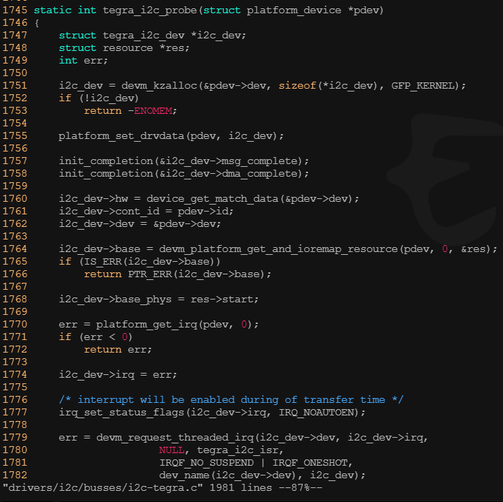
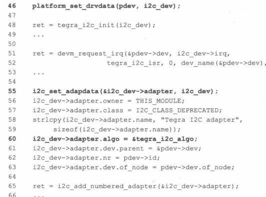
? ? ? ? 其中probe指針指向的tegra_i2c_probe()函數將被調用。以初始化,適配器硬件、申請適配器要的內存、時鐘、中斷等資源,最終注冊適配器。
? ? ?
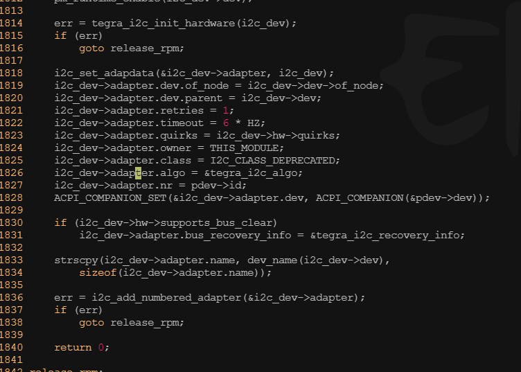
? ? ? ? 上述代碼中提到tegra_i2c_dev結構體可進行適配器所有信息的封裝,類似私有信息結構體。下圖是tegra_i2c_dev結構體的定義。我們在編程中要時刻牢記linux這個編程習慣,這實際上也是面向對象的一種體現。
260 struct tegra_i2c_dev {261 struct device *dev;262 struct i2c_adapter adapter;263 264 const struct tegra_i2c_hw_feature *hw;265 struct reset_control *rst;266 unsigned int cont_id;267 unsigned int irq;268 269 phys_addr_t base_phys;270 void __iomem *base;271 272 struct clk_bulk_data clocks[2];273 unsigned int nclocks;274 275 struct clk *div_clk;276 struct i2c_timings timings;277 278 struct completion msg_complete;279 size_t msg_buf_remaining;280 unsigned int msg_len;281 int msg_err;282 u8 *msg_buf;283 284 struct completion dma_complete;285 struct dma_chan *dma_chan;286 unsigned int dma_buf_size;287 struct device *dma_dev;288 dma_addr_t dma_phys;289 void *dma_buf;290 291 bool multimaster_mode;292 bool atomic_mode;293 bool dma_mode;294 bool msg_read;295 bool is_dvc;296 bool is_vi;297 };?????????tegra_i2c_probe()函數中的platform_set_drvdata(pdev,i2c_dev)和i2c_set_adapterdata(&I2C_dev->adapter,i2c_dev)已經把這個結構體的實例依附到了platform_device和i2c_adapter的私有數據上了,在其他地方只要用到相應的方法就可以把這個結構體的實例取出來。
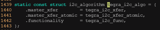
? ? ? ? 從前面的白圖代碼60行可以看出,于i2c適配器對應的i2c_algorithm結構體實例為tera_i2c_algo,下圖給出定義
???????? ?
?
? ? ? ? 上訴代碼第一行指定了Tera I2c總線通信傳輸函數tegra_i2c_xfer(),這個函數非常關鍵,所有在i2c總線上對設備的訪問最終應該由它完成。下圖為這個重要函數以及其依賴的tegra_i2c_xfer_msg()函數的源碼:
1213 static int tegra_i2c_xfer_msg(struct tegra_i2c_dev *i2c_dev,
1214                   struct i2c_msg *msg,
1215                   enum msg_end_type end_state)
1216 {
1217     unsigned long time_left, xfer_time = 100;
1218     size_t xfer_size;
1219     u32 int_mask;
1220     int err;
1221
1222     err = tegra_i2c_flush_fifos(i2c_dev);
1223     if (err)
1224         return err;
1225
1226     i2c_dev->msg_buf = msg->buf;
1227     i2c_dev->msg_len = msg->len;
1228
1229     i2c_dev->msg_err = I2C_ERR_NONE;
1230     i2c_dev->msg_read = !!(msg->flags & I2C_M_RD);
1231     reinit_completion(&i2c_dev->msg_complete);
1232
1233     /*
1234      * For SMBUS block read command, read only 1 byte in the first transfer.
1235      * Adjust that 1 byte for the next transfer in the msg buffer and msg
1236      * length.
1237      */
1238     if (msg->flags & I2C_M_RECV_LEN) {
1239         if (end_state == MSG_END_CONTINUE) {
1240             i2c_dev->msg_len = 1;
1241         } else {
1242             i2c_dev->msg_buf += 1;
1243             i2c_dev->msg_len -= 1;
1244         }
1245     }
1246
1247     i2c_dev->msg_buf_remaining = i2c_dev->msg_len;
1248
1249     if (i2c_dev->msg_read)
1250         xfer_size = i2c_dev->msg_len;
1251     else
1252         xfer_size = i2c_dev->msg_len + I2C_PACKET_HEADER_SIZE;
1253
1254     xfer_size = ALIGN(xfer_size, BYTES_PER_FIFO_WORD);
1255
1256     i2c_dev->dma_mode = xfer_size > I2C_PIO_MODE_PREFERRED_LEN &&
1257                 i2c_dev->dma_buf && !i2c_dev->atomic_mode;
1258
1259     tegra_i2c_config_fifo_trig(i2c_dev, xfer_size);
1260
1261     /*
1262      * Transfer time in mSec = Total bits / transfer rate
1263      * Total bits = 9 bits per byte (including ACK bit) + Start & stop bits
1264      */
1265     xfer_time += DIV_ROUND_CLOSEST(((xfer_size * 9) + 2) * MSEC_PER_SEC,
1266                        i2c_dev->timings.bus_freq_hz);
1267
1268     int_mask = I2C_INT_NO_ACK | I2C_INT_ARBITRATION_LOST;
1269     tegra_i2c_unmask_irq(i2c_dev, int_mask);
1270
1271     if (i2c_dev->dma_mode) {
1272         if (i2c_dev->msg_read) {
1273             dma_sync_single_for_device(i2c_dev->dma_dev,
1274                            i2c_dev->dma_phys,
1275                            xfer_size, DMA_FROM_DEVICE);
1276
1277             err = tegra_i2c_dma_submit(i2c_dev, xfer_size);
1278             if (err)
1279                 return err;
1280         } else {
1281             dma_sync_single_for_cpu(i2c_dev->dma_dev,
1282                         i2c_dev->dma_phys,
1283                         xfer_size, DMA_TO_DEVICE);
1284         }
1285     }
1286
1287     tegra_i2c_push_packet_header(i2c_dev, msg, end_state);
1288
1289     if (!i2c_dev->msg_read) {
1290         if (i2c_dev->dma_mode) {
1291             memcpy(i2c_dev->dma_buf + I2C_PACKET_HEADER_SIZE,
1292                    msg->buf, i2c_dev->msg_len);
1293
1294             dma_sync_single_for_device(i2c_dev->dma_dev,
1295                            i2c_dev->dma_phys,
1296                            xfer_size, DMA_TO_DEVICE);
1297
1298             err = tegra_i2c_dma_submit(i2c_dev, xfer_size);
1299             if (err)
1300                 return err;
1301         } else {
1302             tegra_i2c_fill_tx_fifo(i2c_dev);
1303         }
1304     }
1305
1306     if (i2c_dev->hw->has_per_pkt_xfer_complete_irq)
1307         int_mask |= I2C_INT_PACKET_XFER_COMPLETE;
1308
1309     if (!i2c_dev->dma_mode) {
1310         if (msg->flags & I2C_M_RD)
1311             int_mask |= I2C_INT_RX_FIFO_DATA_REQ;
1312         else if (i2c_dev->msg_buf_remaining)
1313             int_mask |= I2C_INT_TX_FIFO_DATA_REQ;
1314     }
1315
1316     tegra_i2c_unmask_irq(i2c_dev, int_mask);
1317     dev_dbg(i2c_dev->dev, "unmasked IRQ: %02x\n",
1318         i2c_readl(i2c_dev, I2C_INT_MASK));
1319
1320     if (i2c_dev->dma_mode) {
1321         time_left = tegra_i2c_wait_completion(i2c_dev,
1322                               &i2c_dev->dma_complete,
1323                               xfer_time);
1324
1325         /*
1326          * Synchronize DMA first, since dmaengine_terminate_sync()
1327          * performs synchronization after the transfer's termination
1328          * and we want to get a completion if transfer succeeded.
1329          */
1330         dmaengine_synchronize(i2c_dev->dma_chan);
1331         dmaengine_terminate_sync(i2c_dev->dma_chan);
1332
1333         if (!time_left && !completion_done(&i2c_dev->dma_complete)) {
1334             dev_err(i2c_dev->dev, "DMA transfer timed out\n");
1335             tegra_i2c_init(i2c_dev);
1336             return -ETIMEDOUT;
1337         }
1338
1339         if (i2c_dev->msg_read && i2c_dev->msg_err == I2C_ERR_NONE) {
1340             dma_sync_single_for_cpu(i2c_dev->dma_dev,
1341                         i2c_dev->dma_phys,
1342                         xfer_size, DMA_FROM_DEVICE);
1343
1344             memcpy(i2c_dev->msg_buf, i2c_dev->dma_buf, i2c_dev->msg_len);
1345         }
1346     }
1347
1348     time_left = tegra_i2c_wait_completion(i2c_dev, &i2c_dev->msg_complete,
1349                           xfer_time);
1350
1351     tegra_i2c_mask_irq(i2c_dev, int_mask);
1352
1353     if (time_left == 0) {
1354         dev_err(i2c_dev->dev, "I2C transfer timed out\n");
1355         tegra_i2c_init(i2c_dev);
1356         return -ETIMEDOUT;
1357     }
1358
1359     dev_dbg(i2c_dev->dev, "transfer complete: %lu %d %d\n",
1360         time_left, completion_done(&i2c_dev->msg_complete),
1361         i2c_dev->msg_err);
1362
1363     i2c_dev->dma_mode = false;
1364
1365     err = tegra_i2c_error_recover(i2c_dev, msg);
1366     if (err)
1367         return err;
1368
1369     return 0;
1370 }1372 static int tegra_i2c_xfer(struct i2c_adapter *adap, struct i2c_msg msgs[],
1373               int num)
1374 {
1375     struct tegra_i2c_dev *i2c_dev = i2c_get_adapdata(adap);
1376     int i, ret;
1377
1378     ret = pm_runtime_get_sync(i2c_dev->dev);
1379     if (ret < 0) {
1380         dev_err(i2c_dev->dev, "runtime resume failed %d\n", ret);
1381         pm_runtime_put_noidle(i2c_dev->dev);
1382         return ret;
1383     }
1384
1385     for (i = 0; i < num; i++) {
1386         enum msg_end_type end_type = MSG_END_STOP;
1387
1388         if (i < (num - 1)) {
1389             /* check whether follow up message is coming */
1390             if (msgs[i + 1].flags & I2C_M_NOSTART)
1391                 end_type = MSG_END_CONTINUE;
1392             else
1393                 end_type = MSG_END_REPEAT_START;
1394         }
1395         /* If M_RECV_LEN use ContinueXfer to read the first byte */
1396         if (msgs[i].flags & I2C_M_RECV_LEN) {
1397             ret = tegra_i2c_xfer_msg(i2c_dev, &msgs[i], MSG_END_CONTINUE);
1398             if (ret)
1399                 break;
1400             /* Set the msg length from first byte */
1401             msgs[i].len += msgs[i].buf[0];
1402             dev_dbg(i2c_dev->dev, "reading %d bytes\n", msgs[i].len);
1403         }
1404         ret = tegra_i2c_xfer_msg(i2c_dev, &msgs[i], end_type);
1405         if (ret)
1406             break;
1407     }
1408
1409     pm_runtime_put(i2c_dev->dev);
1410
1411     return ret ?: i;
1412 }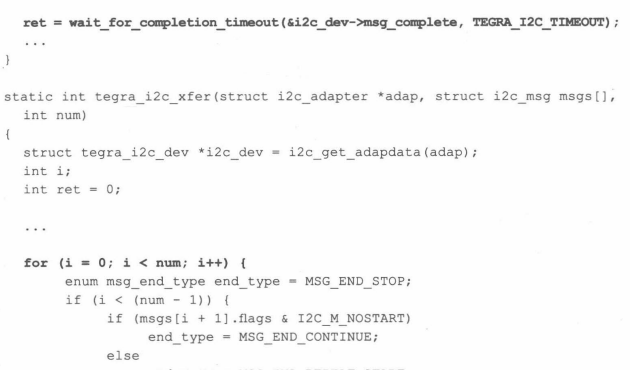
? ? ? ? 從代碼層面上看,第35行的for循環遍歷所有的i2c_msg,每個i2c_msg則由tegra_i2c_xfer_msg()函數處理,它每次發起硬件操作后,實際上需要通過wait_for_completion_timeout()等待傳輸的完成,因此這里面就會有一個被調度出去的過程。中斷到來且i2c的包傳輸結束的時候,就是喚醒這個睡眠進程的時候。
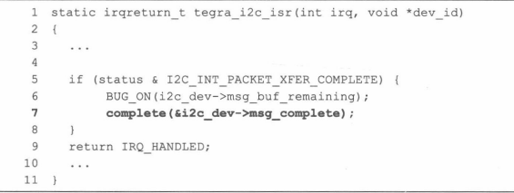
??
六、? ? ? ? 總結?
? ? ? ? linux的i2c驅動體系相當復雜,它主要由3部分組成,即i2c核心、i2c總線驅動和i2c設備驅動。I2c核心是i2c總線驅動和i2c設備驅動的中間樞紐,它以通用的、與平臺的無關的接口是實現了i2c中設備與適配器的溝通。i2c總線驅動填充i2c_adapter和i2c_algorithm結構體,i2c設備驅動填充i2c_driver結構體并實現其本身所對應設備類型的驅動。
? ? ? ? 另外,系統中i2c-dev.c文件定義的主設備號89的設備可以方便地給應用程序提供讀寫i2c設備寄存器的能力,使得工程師在大多數時候并不需要為具體的i2c設備驅動定義文件操作接口。
????????
?????????
?????????
????????
? ? ? ??


類圖)


排序算法—交換排序(快速排序)(動圖演示))


)


