PBR×BRDF原理&Unity實現深入淺出_嗶哩嗶哩_bilibili
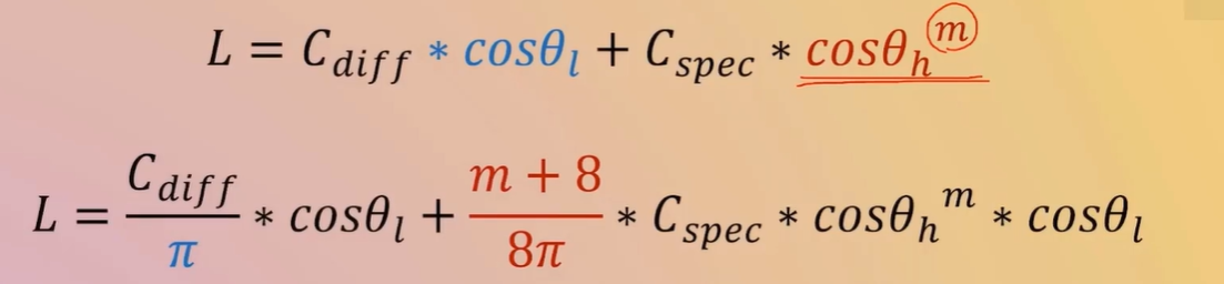
進行改進
一個像素點對應一個范圍內的 一個微表面--一個由無數個起起伏伏的結構組成的物理結構
屏幕上的每一個像素點,在渲染時通常會被視為一個“微表面”的代表
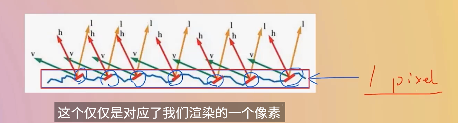
比如在這個圖中,只關心紅色的區域
float3 R = reflect(-L, N);  // R 是 L 關于法線 N 的反射方向
float spec = pow(saturate(dot(R, V)), shininess);
xxx
半角更柔和,無需第四reflect vector,所以更適合做擴展--Cook-Torrance 等微表面模型
現代 PBR / BRDF,Half Vector 是必需的(Cook-Torrance 中 H 是中心變量)float3 H = normalize(L + V); // H 是光線方向 L 和視線方向 V 的中間向量
float spec = pow(saturate(dot(N, H)), shininess);
GGX 比 Blinn 更真實
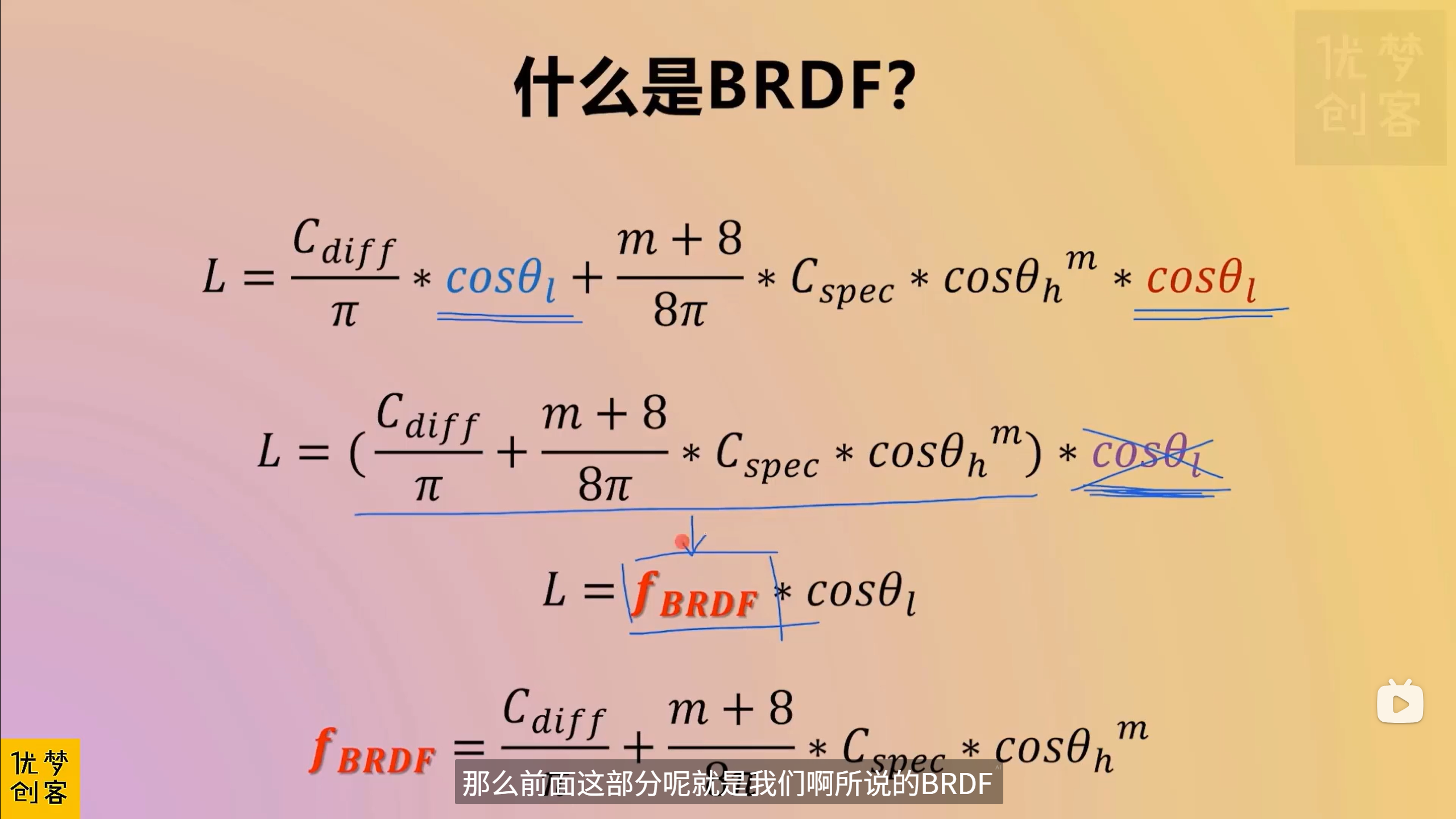
對于高光顏色的額外處理,整體起個名字--就是NDF normal distribution function?
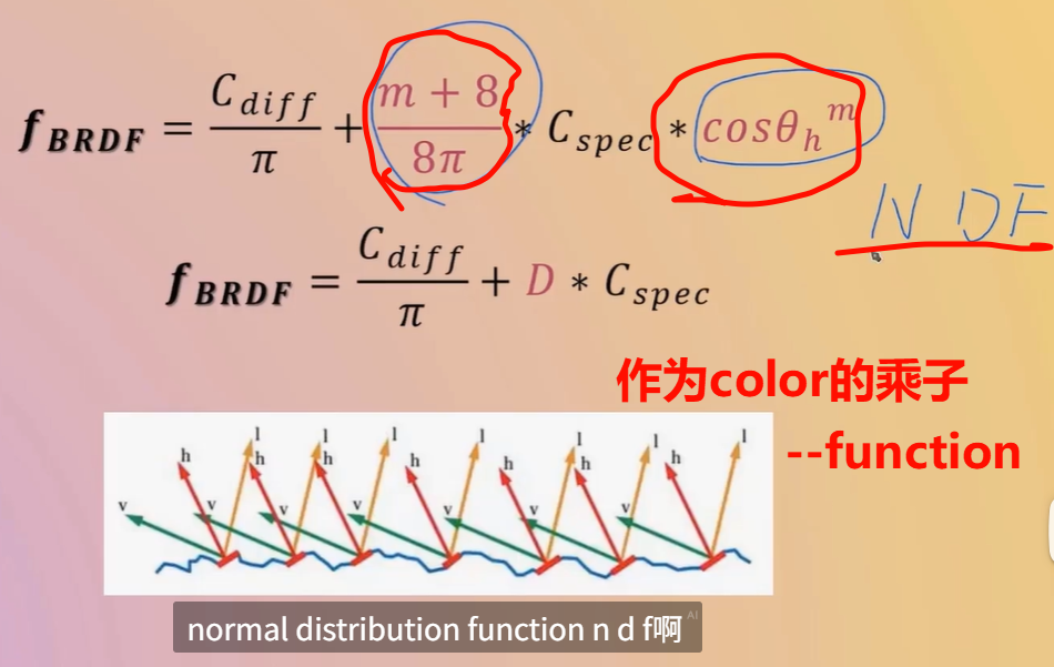
“某方向上的微鏡面法線出現的概率密度”,即在單位立體角內,有多少微鏡面法線與該方向對齊。這是描述表面粗糙程度的統計工具
Fresnel 項 F、幾何遮蔽項 G 一起構成 Cook?Torrance 等物理基礎的鏡面反射模型中的 D(分布項)
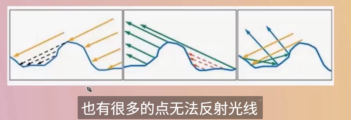
目前對于微表面,并沒有加入表面本身的幾何遮擋關系
-
入射角越傾斜(越斜著看),反射光比例越大 → 更亮、更specular
-
入射角越垂直(正對看),反射光比例越小 → 更暗、更diff
-
是 角度相關的顏色變化核心因素
F 描述反射顏色比例,D 描述高光形狀,G 描述遮擋和遮蔽
你問的是哪種“光追”?
“用一個 Shader 模擬出光追的感覺”
比如:
-
屏幕空間反射(SSR)
-
屏幕空間全局光照(SSGI)
-
Ray Marching 軟陰影 / 反射 / 折射
-
Path Tracing 預覽器(離線渲染風格)
? 那么答案是:可以,可以只用 Shader(或者 Shader + Compute)實現近似“光追”表現
“真的發出一條物理射線,穿過場景,檢測與三角形的精確交點”(即 DXR)
那就要:
-
? 支持 GPU 硬件加速的光線追蹤(DXR)
-
? Unity 的 HDRP 渲染管線
-
? 使用 RayTracingShader 資源文件,不是傳統
.shader文件
👉 這就不是“一個普通 Shader 就能搞定”的事情了,而是 Unity 2021+ 在 HDRP 下才支持的高級功能。
xxx
SV_DispatchThreadID
SV_DispatchThreadID - Win32 apps | Microsoft Learn
SV_DispatchThreadID is the sum of SV_GroupID * numthreads and GroupThreadID.?
-
Dispatch(2,2,2):意味著你在 CPU 端對每個維度都分配了 2 個線程組(groups)。 -
[numthreads(3,3,3)]:意味著每個線程組內部,在每個維度上又有 3 個線程。
所以:
-
GPU 會在三個維度上創建
(2 groups) × (3 threads per group) = 6個全局線程索引單位。 -
因為索引從 0 開始,所以范圍是
0, 1, 2, 3, 4, 5,即 “0..5”。
換句話說:
-
id.x的取值范圍是 0 到 5 -
id.y也是 0 到 5 -
id.z也是 0 到 5
這反映了每個維度上:共計 2 × 3 = 6 的線程覆蓋范圍。
全局線程 ID(即 SV_DispatchThreadID)的最大值為 (groupCount * threadsPerGroup) – 1,所以總數各自為 a*x, b*y, c*z,
但這三個維度一起形成了 線程的唯一 3D 全局坐標。并不是說存在三個 Buffer,它們是組合起來確定線程的“定位”。
| 概念 | 含義 |
|---|---|
Dispatch(A,B,C) | CPU 發起的線程組數量 |
[numthreads(X,Y,Z)] | 每個線程組內部的線程數量 |
id.x | 全局 X 軸線程索引,范圍 0..(A×X - 1) |
id.y | 全局 Y 軸線程索引,范圍 0..(B×Y - 1) |
id.z | 全局 Z 軸線程索引,范圍 0..(C×Z - 1) |
| 三者合并 | 構成一個線程在三維空間中的唯一位置(uint3) |
我去,三萬多條三角形,,居然只10,ms不到,,牛哭了
Compute Shaders
For 40,000 points that's 2.56 million bytes—roughly 2.44MiB—that has to be copied to the GPU every time the points are drawn. URP has to do this twice per frame, once for shadows and once for the regular geometry.?BRP?has to do it at least three times, because of its extra depth-only pass, plus once more for every light besides the main directional one.
it would be ideal if that data only exists on the GPU side.?
the CPU can no longer calcuate the positions, the GPU has to do it instead. Fortunately it is quite suited for the task.
https://docs.unity3d.com/ScriptReference/SerializeField.html
When Unity serializes your scripts, it only serializes public fields. If you also want Unity to serialize your private fields you can add the SerializeField attribute to those fields.
To store the positions on the GPU we need to allocate space for them. We do this by creating a?ComputeBuffer?object
https://docs.unity3d.com/ScriptReference/ComputeBuffer.html
Compute buffers are always supported in compute shaders. Compute shader support can be queried runtime using?SystemInfo.supportsComputeShaders. See the?Compute Shaders?Manual page for more information about platforms supporting compute shaders. In regular graphics shaders the compute buffer support requires minimum?shader model 4.5.
A compute buffer contains arbitrary untyped data. We have to specify the exact size of each element in bytes, via a second argument.?
positionsBuffer = new ComputeBuffer(resolution * resolution, 3 * 4);store 3D position vectors, which consist of three?float?numbers, so the element size is three times four bytes.
Thus 40,000 positions would require 0.48MB or roughly 0.46MiB of GPU memory.
This gets us a compute buffer, but these objects do not survive hot reloads, which means that if we change code while in play mode it will disappear.?
deal with this by replacing the?Awake?method with an?OnEnable?method, which gets invoked each time the component is enabled.
This happens right after it awakens—unless it's disabled—and also after a hot reload is completed.
Besides that we should also add a companion?OnDisable?method, which gets invoked when the component is disabled, which also happens if the graph is destroyed and right before a hot reload.?
Have it release the buffer, by invoking its?Release?method. This indicates that the GPU memory claimed by the buffer can be freed immediately.
“熱重載”(Hot Reload)是 Unity 編輯器中非常實用的一項功能,它允許你在**游戲仍在運行(Play Mode)**或編輯器處于打開狀態時,修改并保存腳本后無需重啟,Unity 會自動應用這些更改。
為什么推薦用 OnEnable() 而不是 Awake()?
-
Awake()通常只在腳本加載時執行一次,但在熱重載后 Unity 的對象生命周期會被重置,你很可能不會得到一個新的 Awake 調用。 -
相對而言,
OnEnable()會在組件每次被啟用或在熱重載完成后調用,這使它成為重新初始化臨時對象(例如 Compute Buffer)更可靠的地方。
由于在此之后我們將不再使用此特定對象實例,因此將字段顯式設置為引用null是個好主意。這使得在運行模式下,如果我們的圖被禁用或銷毀,對象在下一次運行時可以被Unity的內存垃圾回收過程回收。
void OnDisable () {positionsBuffer.Release();positionsBuffer = null;}
如果沒有任何引用指向該對象,垃圾回收器最終會回收它。但這種情況發生的時間是任意的。最好盡快顯式釋放它,以避免內存堵塞。
為了在GPU上計算位置,我們必須為其編寫一個腳本,具體來說是一個計算著色器。Create one via?Assets / Create / Shader / Compute Shader。它將成為我們FunctionLibrary類的GPU等效物,因此也命名為FunctionLibrary。雖然它被稱為著色器并使用HLSL語法,但它作為一個通用程序運行,not a as regular shader used for rendering things.
GPU hardware contains compute units that always run a specific fixed amount of threads in lockstep.這些被稱為warp或wavefront
?If the amount of threads of a group is less than the warp size some threads will run idle, wasting time. If the amount of threads instead exceeds the size then the GPU will use more warps per group. In general 64 threads is a good default, as that matches the warp size of AMD GPUs while it's 32 for NVidia GPUs, so the latter will use two warps per group.?實際上,硬件更復雜,可以對線程組做更多的事情,但這對我們簡單的圖形不相關。
numthreads的三個參數可以用來在一維、二維或三維中組織線程。例如,(64, 1, 1)給我們提供了一個維度的64個線程,而(8, 8, 1)給我們相同數量的線程,但以2D 8×8正方形網格的形式呈現。由于我們根據2D UV坐標定義點,因此讓我們使用后者選項。
[numthreads(8, 8, 1)]
Each thread is identified by a vector of three unsigned integers, which we can access by adding a?uint3?parameter to our function.
我們可以將線程標識符轉換為UV坐標,如果我們知道圖形的步長。為它添加一個名為_Step的計算機著色器屬性,就像我們為表面著色器添加_Smoothness屬性一樣。
https://www.youtube.com/watch?v=jbuGYhRWAkY
MaterialPropertyBlock - Unity 腳本 API
MaterialPropertyBlock is used by?Graphics.RenderMesh?and?Renderer.SetPropertyBlock. Use it in situations where you want to draw multiple objects with the same material, but slightly different properties. For example, if you want to slightly change the color of each mesh drawn. Changing the render state is not supported.
Unity 的地形引擎使用 MaterialPropertyBlock 繪制樹;它們全都使用 相同材質,但是每棵樹具有不同的顏色、縮放和風力系數。
Note that this is not compatible with?SRP Batcher. Using this in the Universal Render Pipeline (URP), High Definition Render Pipeline (HDRP) or a custom render pipeline based on the Scriptable Render Pipeline (SRP) will likely result in a drop in performance.
var props = new MaterialPropertyBlock();
renderer.GetPropertyBlock(props);
props.SetColor("_Color", Color.red);
renderer.SetPropertyBlock(props);
這段代碼演示了如何為某個 Render 對象設置專屬顏色,而無需創建新材質。
Unity 的 GPU 間接實例化渲染(Instanced Indirect Rendering)
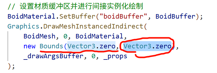
// 設置材質緩沖區并進行間接實例化繪制BoidMaterial.SetBuffer("boidBuffer", BoidBuffer);Graphics.DrawMeshInstancedIndirect(BoidMesh, 0, BoidMaterial,new Bounds(Vector3.zero, Vector3.one * 1000),_drawArgsBuffer, 0, _props);// 將 GPU 中的 BoidBuffer 綁定到材質,以便 Shader 內訪問
BoidMaterial.SetBuffer("boidBuffer", BoidBuffer);// 用 GPU 進行間接實例化繪制
Graphics.DrawMeshInstancedIndirect(
? BoidMesh, ? ? ? ? ? ?// 要實例化的 Mesh
? 0, ? ? ? ? ? ? ? ? ? // 子網格索引(一般為 0)
? BoidMaterial, ? ? ? ?// 使用的材質
? new Bounds(Vector3.zero, Vector3.one * 1000), ?// 包圍盒,用于剔除優化
? _drawArgsBuffer, ? ? // 包含繪制參數的 GPU 緩沖(Indirect Args)
? 0, ? ? ? ? ? ? ? ? ? // 參數緩沖偏移
? _props ? ? ? ? ? ? ? // 可選的 MaterialPropertyBlock,用于覆蓋材質屬性
);
GPU 加速批量繪制(Instanced Indirect)
傳統方式中,每幀 CPU 都會上傳實例數據給 GPU,耗性能。
DrawMeshInstancedIndirect 方法則讓渲染指令和實例數量來源于 GPU 緩沖 _drawArgsBuffer
GPU 自行決定繪制多少實例
參數緩沖(argsBuffer)
該緩沖需要包含 5 個組成的整數數組,按照順序分別代表:
-
每個實例的索引數量(index count)
-
實例總數
-
開始索引位置(start index)
-
基礎頂點偏移(base vertex)
-
開始實例偏移(start instance)
public struct GPUBoid_Draw
{public Vector3 position;      // 3 × 4 = 12 bytespublic Vector3 direction;     // 12 bytespublic float noise_offset;    // 4 bytespublic Vector3 padding;       // 12 bytes
}
position + direction = 24 bytesnoise_offset = 4 bytes → 總共 28 bytesGPU 更傾向于 16 字節對齊,所以下面會進行對齊填充為了讓結構體對齊到 32 bytes(即 2 個 16?byte 塊),你添加了 padding,這使得整個結構體容量為 24 + 4 + 12 = 40 bytes,在 GPU 端更容易對齊甚至安全訪問。
對齊問題的風險
如果忽視對齊規則,很可能導致:
-
讀取異常或數據錯位:例如
noise_offset實際讀取的是direction的部分數據。 -
GPU 崩潰或異常渲染:尤其使用
StructuredBuffer<T>時,對齊偏差會引起 shader 崩潰或數據錯亂。
舉個簡單的例子來說明
假設你定義了這樣一個 struct:
struct Example {Vector3 a; ? ?// 占 12 字節float b; ? ? ?// 占 4 字節float c; ? ? ?// 占 4 字節
}
整體看起來占 20 字節,但 GPU 可能仍然會按 16 字節的塊來讀取:
-
第一塊(16 字節)包含
a(12 字)和b(4 字); -
第二塊(16 字節)只剩下
c(4 字),剩余 12 字節是空的(未定義)。 -
如果沒有填充,GPU “無法知道”
c應該讀在哪里,就會出錯。
bounds 參數:它為什么必須要提供?
-
視錐剔除(Frustum Culling)
bounds參數定義了一個包圍盒(AABB,Axis-Aligned Bounding Box),它用于告訴渲染系統所有要繪制實例的空間范圍。引擎會基于此計算是否需要在當前幀渲染這些實例
→ 如果這個包圍盒完全或部分在相機視錐內,這才可能執行繪制操作;如果包圍盒完全在視野之外,那么整個實例繪制就會被剔除以節省性能。 -
批處理與 GPU 調度
在 GPU 調用中傳入bounds明確告訴引擎在哪個區域中要進行實例化繪制,有助于引擎更好地組織和優化 GPU 工作,尤其是在使用大規模實例渲染(instanced indirect)技術時。
-
BoidMesh:要渲染的網格模型。 -
BoidMaterial:使用的材質及其著色器定義,管理視覺表現。 -
bounds:表示所有實例在世界空間里可能占據的范圍。 -
_drawArgsBuffer:一個 GPU 計算緩沖區(ComputeBuffer),包含了DrawMeshInstancedIndirect所需的數據,如實例數量、頂點索引起始等(通常通過 Compute Shader 填充)。 -
_props:一個材質屬性塊(MaterialPropertyBlock),允許傳遞實例級別或批次級別的 Shader 數據,比如變換矩陣、顏色等。
這些參數共同構成了 GPU 渲染指令的完整信息流:
(mesh, material, instance count/arguments, world-space region, shader properties)
假設你用它來渲染成百上千只“Boid”鳥群,每只有不同的位置和形態:
-
ComputeShader 計算每幀的 boid 位置、旋轉等數據,并寫入
_drawArgsBuffer與_props。 -
然后調用
Graphics.DrawMeshInstancedIndirect,傳入這些數據。 -
Unity 使用你設定的
bounds(例如(0,0,0), size (1000,1000,1000))告訴 GPU 這些 boid 可能都散布在這個范圍里。 -
若這個包圍盒根本不在鏡頭里,那么一切實例渲染就會被省略,提高渲染效率。
-
bounds參數關鍵在于 向渲染系統聲明實例的空間分布范圍,以便進行正確的剔除與調度優化。 -
它與其他參數(mesh、material、draw buffer、properties)一同構成了 GPU 批量實例繪制的完整邏輯鏈條。
唯一發現的影響就是這樣的,bound至少在這個問題上有解決的,也的確和剔除什么的有點關系
_drawArgsBuffer(ComputeBuffer)
-
作用:
-
這是一個 GPU 緩存區,存儲了繪制參數,比如實例數(instance count)、每實例的頂點偏移、索引偏移等控制繪制過程的底層數據。
-
通常,由 Compute Shader 每幀更新,提升 GPU-side 實例繪制的效率。
-
-
用途限制:
-
它只負責繪制的數量和方式,不包含材質或 Shader 參數等內容。
-
MaterialPropertyBlock
-
作用:
-
用于在渲染調用層面動態傳遞材質參數,比如每個實例的顏色、位置變換、貼圖索引、特效參數等。
-
通過它可修改材質屬性而不創建新的材質實例,節省性能開銷。
-
-
與實例屬性結合:
-
比如你想讓每只 boid 顏色不同、朝向不同,或具備個性化的動畫參數,就會用 MaterialPropertyBlock 將這些信息傳入 Shader。
-
-
_drawArgsBuffer管理的是“幾個實例要繪制、繪制方式”; -
MaterialPropertyBlock管理的是“這些實例呈現什么效果、使用哪些材質參數”。
-
即使你把所有數據寫入 ComputeBuffer,也難以直接在傳統 Shader 里訪問和解析,而且 Shader 不直接讀取 ComputeBuffer 中的數據作為材質屬性。
-
而 MaterialPropertyBlock 是 Unity 渲染機制內建的方式,專門為每個渲染調用定制屬性值。
MaterialPropertyBlock 將具體的 per-instance Shader 參數(如 Matrix、Color)封裝傳入 Draw 調用。
UNITY_PROCEDURAL_INSTANCING_ENABLED
這個宏 只在使用 Graphics.DrawMeshInstancedIndirect(或 Procedural Instancing)時啟用。它與普通 GPU Instancing 的宏不同,而是專用于更底層、更靈活的實例化路徑(即“procedural”方式)。
通常,你需要在 Shader 中寫上:
#pragma multi_compile_instancing
#pragma instancing_options procedural:setup
procedural:setup 會把你的 setup() 函數(或指定函數)當作處理每個實例數據的入口,并激活宏 UNITY_PROCEDURAL_INSTANCING_ENABLED
------所以_drawArgsBuffer就是用來標記這個shader的
正確初始化 out 類型的 Input 結構體(通常被命名為 o 或 data)
void vert(inout appdata_full v, out Input data)
{
? ? UNITY_INITIALIZE_OUTPUT(Input, data);
}
UNITY_INITIALIZE_OUTPUT 的作用是什么?
-
它是 Unity 提供的一個宏,用于給輸出結構體(如
Input data)中的所有字段賦初值(通常為零)。 -
在某些平臺(尤其是 D3D、Mobile)上,如果輸出結構體的字段沒有被完全初始化,就會引發渲染警告甚至錯誤。使用該宏能有效避免這些問題。
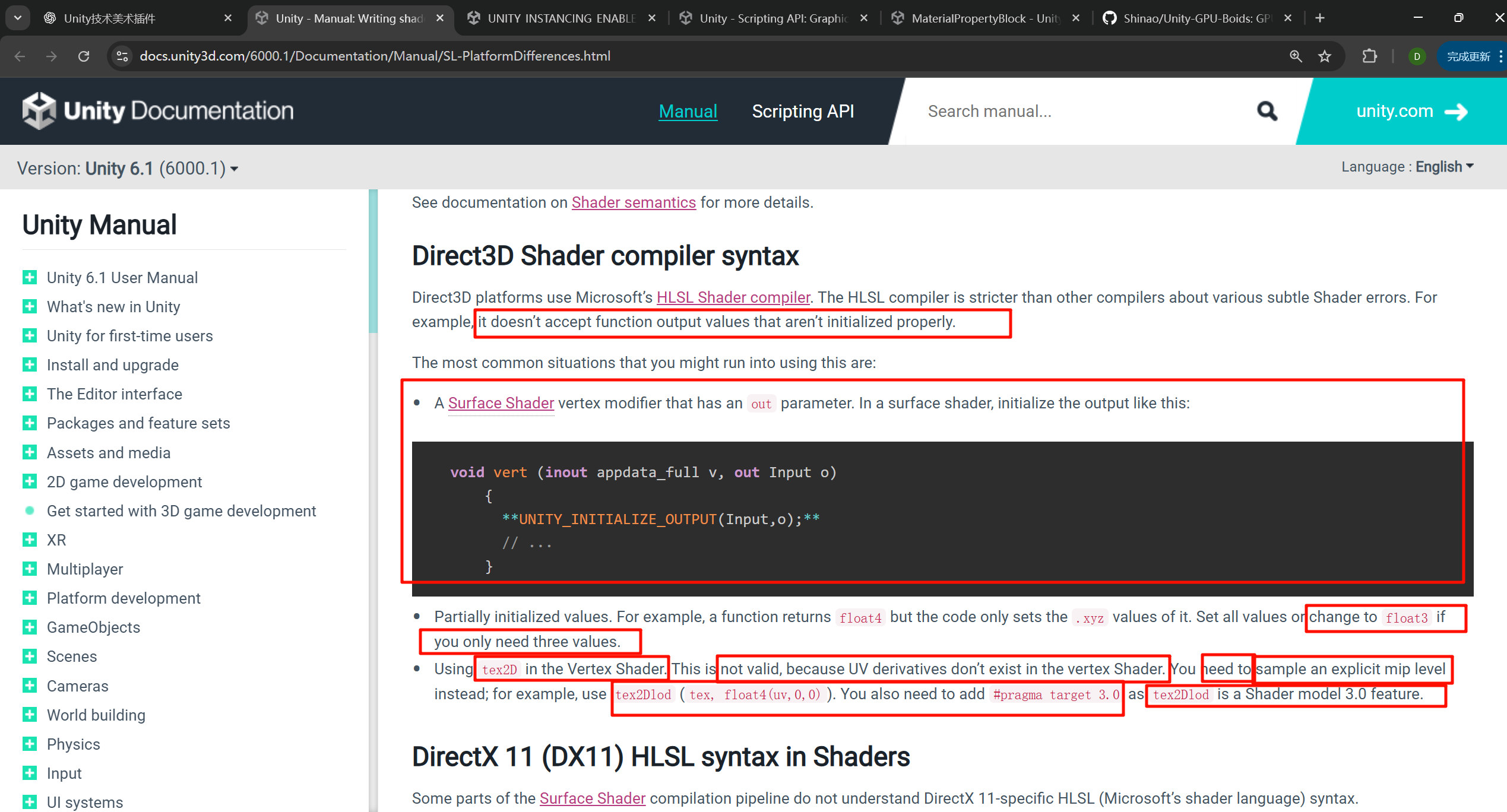
為了dx
Direct3D platforms use Microsoft’s?HLSL Shader compiler. The HLSL compiler is stricter than other compilers about various subtle Shader errors. For example, it doesn’t accept function output values that aren’t initialized properly.
look_at_matrix
// 計算朝向矩陣float4x4 look_at_matrix(float3 at, float3 eye, float3 up){// 計算 z 軸方向(目標點到觀察點的方向向量)float3 zaxis = normalize(at - eye);// 計算 x 軸方向(up 向量與 z 軸的叉積,表示水平向量)float3 xaxis = normalize(cross(up, zaxis));// 計算 y 軸方向(z 軸與 x 軸的叉積,表示垂直向量)float3 yaxis = cross(zaxis, xaxis);// 返回 4x4 矩陣,表示從 eye 看向 at 的變換矩陣return float4x4(xaxis.x, yaxis.x, zaxis.x, 0, // 第一列:x 軸方向xaxis.y, yaxis.y, zaxis.y, 0, // 第二列:y 軸方向xaxis.z, yaxis.z, zaxis.z, 0, // 第三列:z 軸方向0, 0, 0, 1 // 第四列:齊次坐標);}典型的 “Look?At” 朝向矩陣 構造函數(常用于生成相機或物體朝向目標的旋轉矩陣)
三個輸入參數—目標位置 (at)、觀察者位置 (eye) 和 上方向向量 (up)
轉化為一個 4×4 的變換矩陣(旋轉變換)
| x.x, y.x, z.x, 0 |
| x.y, y.y, z.y, 0 |
| x.z, y.z, z.z, 0 |
| 0, ? 0, ? 0, ? 1 |
按照 HLSL “行主序”解析是正確的。在 Unity 中,這樣的矩陣設置表現為首三列是旋轉軸,最后一列是齊次(平移為零,保持 1)。
-----首先搞清楚坐標系,是腳本的本地坐標系
HLSL 中,如果你用 float3 與 float4x4 相乘,系統默認將該 float3 當作 float4(x, y, z, 0) 來處理——也就是說,默認設置了 w = 0
這意味著該向量不會受到矩陣中的平移分量影響,因為 w = 0 的情況下,平移那一行的計算乘積為零,不會加上任何偏移值。
因此,整個變換只會應用旋轉與縮放部分,產生的是一個旋轉后的向量。
| 輸入類型 | 輸出效果 |
|---|---|
float3 × 4×4 矩陣(無平移,或平移有但 w = 0) | 純旋轉(+ 縮放)結果 |
float4(x, y, z, 1) × 4×4 矩陣 | 包含平移的完整變換 |
假設你有一個方向向量要在 Shader 中旋轉但不想添加任何位移,此時你直接寫:
HLSL 會自動當作 float4(oldDir, 0),所以自然只會產生旋轉后的結果。
一個向量的第四位只有0和1,如果是1,此時參與矩陣變換,沒有則無,如果矩陣中有不是0001的第四行和第四列,這個向量就一定會參與位移
w = 1 代表“點”,因此變換中會包括平移;w = 0 代表“向量”,不會受到平移部分的影響。
“If w = 0, then the translation part is ignored... if w = 1, the point is translated... if w = n, translation is scaled by n.”
— from GameDev.net discussion Unity Community+8GameDev+8GameDev+8
在數學上,使用 w = 1 搭配轉換矩陣,可以實現“點加位移”,而 w = 0 時則只執行線性變換(如旋轉),不包含平移。
這是齊次坐標系統的標準用法,非常適合于圖形渲染管線。
https://docs.unity3d.com/410/Documentation/ScriptReference/Matrix4x4.MultiplyPoint.html
Returns a position?v?transformed by the current fully arbitrary matrix. If the matrix is a regular 3D transformation matrix, it is much faster to use?MultiplyPoint3x4?instead.?MultiplyPoint?is slower, but can handle projective transformations as well.
xxxxx
BoidMaterial.SetBuffer("boidBuffer", BoidBuffer);
為什么是Material類去綁定而不是shader類呢,明明計算的邏輯是寫在shader里的
背后,體現了 Unity 的面向材質(Material-oriented)渲染機制。
-
Shader 是不具狀態的程序模板;
-
Material 是 Shader 的具體實例,包含該 Shader 使用的參數(如貼圖、顏色、緩沖數據等)。
因此,緩沖區(ComputeBuffer)必須通過 Material 才能綁定給具體的渲染調用。
Material.SetBuffer:在 GPU 渲染調用中傳參
Unity 的 Material.SetBuffer(string name, ComputeBuffer value) API 的職責是將 ComputeBuffer 綁定到材質的某個屬性名(比如 "boidBuffer"),然后在實際的渲染調用中,Shader 便能讀取這個緩沖區
你可能會問:為什么不是寫在 Shader 里?原因如下:
-
Shader 是靜態的模板,不管理具體緩沖;
-
Material 才是實例化 Shader 并攜帶參數的東西;
-
只有通過 Material 才能在渲染階段將緩沖數據傳遞給 GPU。
與 ComputeShader 的 SetBuffer 區別
雖然代碼中邏輯是在 ComputeShader 中執行,但渲染的 Shader(例如用于 Instancing 或普通渲染的 Surface Shader)并不會自動從 ComputeShader 拿緩沖。需要顯式地綁定到 Material 上。
computeShader.SetBuffer(kernel, "boidBuffer", BoidBuffer);
...
BoidMaterial.SetBuffer("boidBuffer", BoidBuffer);
這是兩步流程:先 GPU 計算出數據,再通過 Material 把數據傳給渲染 Shader。


:用 ProgressBar+Timer 打造動態進度展示功能)
)


)


)