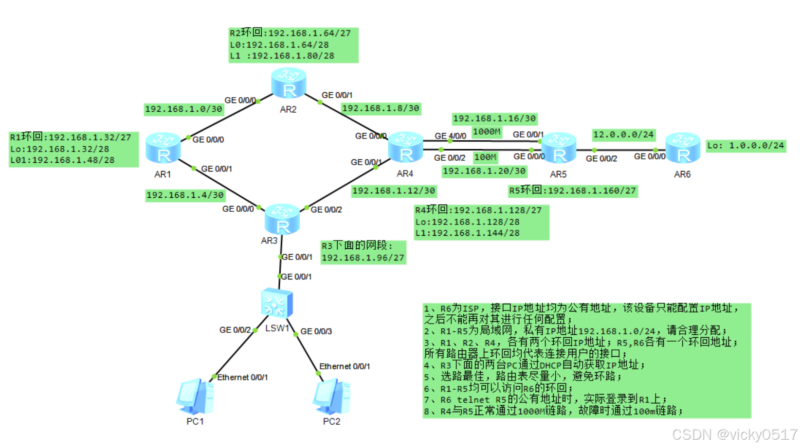
實驗拓撲圖如下:
實驗配置思路如下:
1、網段劃分、配置IP地址
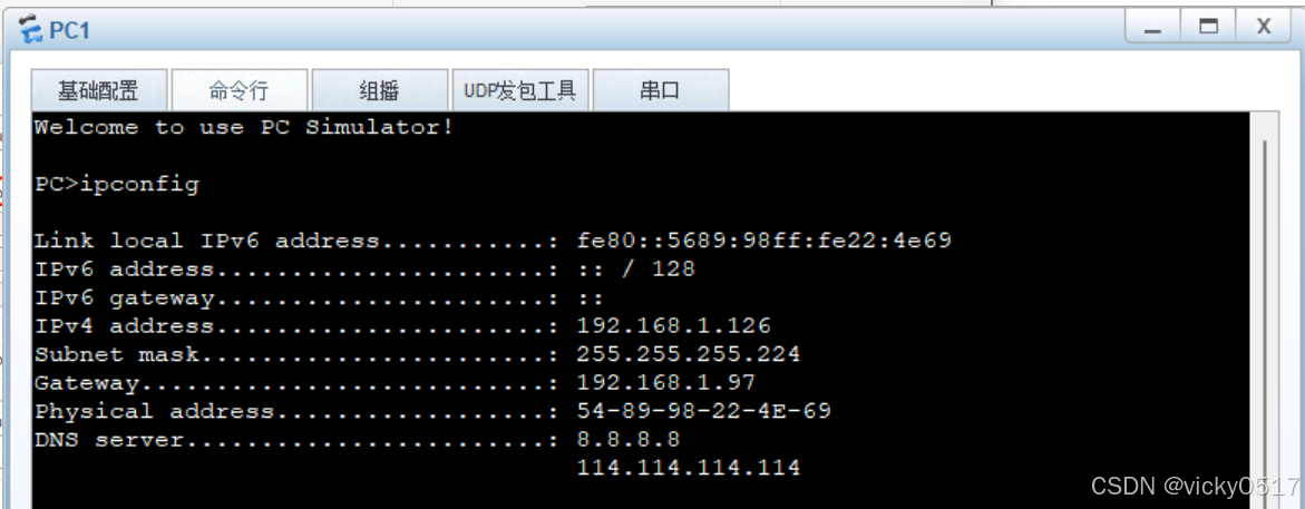
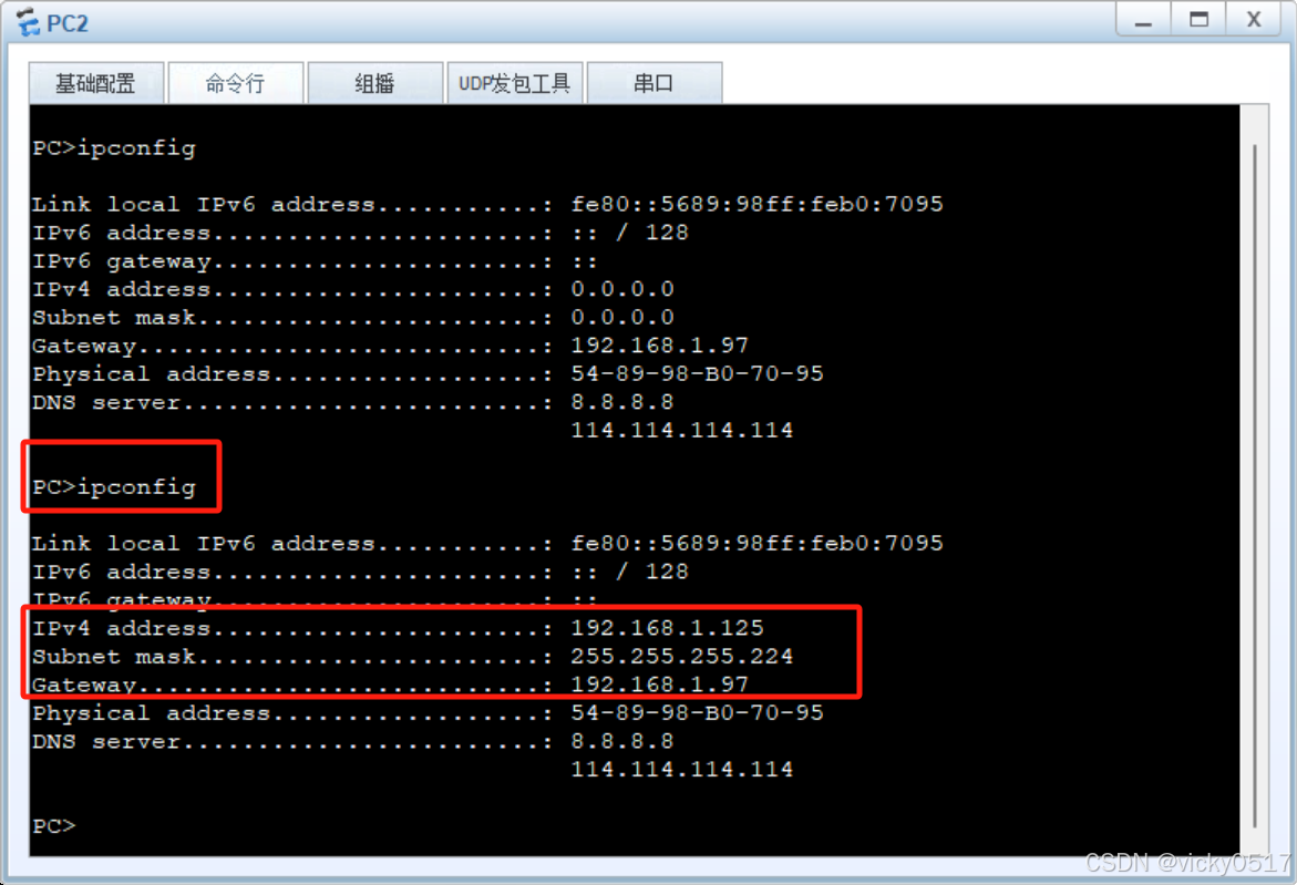
2、配置DHCP,使客戶端獲得ip地址
3、配置靜態明細路由,內網全網通
4、配置空接口防環
5、配置優先級,實現選路最佳
6、配置缺省路由,實現公網通
7、配置nat配置內網訪問公網
8、做NAT SERVER,發布內網服務器服務
一、網段劃分、配置IP地址
拓撲圖中骨干鏈路有6條,實驗要求路由表盡量小,則R1、R2、R4的兩條環回需匯總為一條環回,R5、R6各一條環回。
因此,基于192.168.1.0/24的網段需向主機位借3位為網絡位。網段劃分如下:
| 192.168.1.0/24 | 骨干鏈路 192.168.1.0/27 | 192.168.1.0/30 192.168.1.4/30 192.168.1.8/30 192.168.1.12/30 192.168.1.16/30 192.168.1.20/30 |
| R1環回 192.168.1.32/27 | 192.168.1.32/28 192.168.1.48/28 | |
| R2環回 192.168.1.64/27 | 192.168.1.64/28 192.168.1.80/28 | |
| R3用戶網段 192.168.1.96/27 | ||
| R4環回 192.168.1.128/27 | 192.168.1.128/28 192.168.1.144/28 | |
| R5環回 192.168.1.160/27 | ||
配置R1-R6的IP地址:
[R1]
[R1]int g0/0/0
[R1-GigabitEthernet0/0/0]ip add 192.168.1.1 30
[R1-GigabitEthernet0/0/0]int g0/0/1
[R1-GigabitEthernet0/0/1]ip add 192.168.1.5 30
[R1]int lo1
[R1-LoopBack1]ip add 192.168.1.33 28
[R1-LoopBack1]int lo2
[R1-LoopBack2]ip add 192.168.1.49 28
[R1]dis ip int br
Interface                         IP Address/Mask      Physical   Protocol
GigabitEthernet0/0/0              192.168.1.1/30       up         up
GigabitEthernet0/0/1              192.168.1.5/30       up         up
GigabitEthernet0/0/2              unassigned           down       down
LoopBack1                         192.168.1.33/28      up         up(s)
LoopBack2                         192.168.1.49/28      up         up(s)
NULL0                             unassigned           up         up(s)
[R2]int g0/0/0
[R2-GigabitEthernet0/0/0]ip add 192.168.1.2 30
[R2-GigabitEthernet0/0/0]int g0/0/1
[R2-GigabitEthernet0/0/1]ip add 192.168.1.9 30
[R2]int lo1
[R2-LoopBack1]ip add 192.168.1.65 28
[R2-LoopBack1]int lo2
[R2-LoopBack2]ip add 192.168.1.81 28[R3]int g0/0/0
[R3-GigabitEthernet0/0/0]ip add 192.168.1.6 30
[R3-GigabitEthernet0/0/0]int g0/0/2
[R3-GigabitEthernet0/0/2]ip add 192.168.1.13 30
[R3-GigabitEthernet0/0/2]int g0/0/1
[R3-GigabitEthernet0/0/1]ip add 192.168.1.97 27[R4]int g0/0/0
[R4-GigabitEthernet0/0/0]ip add 192.168.1.10 30
[R4-GigabitEthernet0/0/0]int g0/0/1
[R4-GigabitEthernet0/0/1]ip add 192.168.1.14 30
[R4-GigabitEthernet0/0/1]int g0/0/2
[R4-GigabitEthernet0/0/2]ip add 192.168.1.21 30
[R4-GigabitEthernet0/0/2]int g4/0/0
[R4-GigabitEthernet4/0/0]ip add 192.168.1.17 30
[R4]int lo1
[R4-LoopBack1]ip add 192.168.1.129 28
[R4-LoopBack1]int lo2
[R4-LoopBack2]ip ad 192.168.1.145 28
[R4]dis ip in brief
Interface IP Address/Mask Physical Protocol
GigabitEthernet0/0/0 192.168.1.10/30 up up
GigabitEthernet0/0/1 192.168.1.14/30 up up
GigabitEthernet0/0/2 192.168.1.21/30 up up
GigabitEthernet4/0/0 192.168.1.17/30 up up
GigabitEthernet4/0/1 unassigned down down
GigabitEthernet4/0/2 unassigned down down
GigabitEthernet4/0/3 unassigned down down
LoopBack1 192.168.1.129/28 up up(s)
LoopBack2 192.168.1.145/28 up up(s)
NULL0 unassigned up up(s)
[R5]int g0/0/0
[R5-GigabitEthernet0/0/0]ip add 192.168.1.22 30
[R5-GigabitEthernet0/0/0]int g0/0/1
[R5-GigabitEthernet0/0/1]ip add 192.168.1.18 30
[R5-GigabitEthernet0/0/1]int g0/0/2
[R5-GigabitEthernet0/0/2]ip add 12.0.0.1 24
[R5]int lo1
[R5-LoopBack1]ip add 192.168.1.161 27
[R5]dis ip int br
Interface                         IP Address/Mask      Physical   Protocol
GigabitEthernet0/0/0              192.168.1.22/30      up         up
GigabitEthernet0/0/1              192.168.1.18/30      up         up
GigabitEthernet0/0/2              12.0.0.1/24          up         up
LoopBack1                         192.168.1.161/27     up         up(s)
NULL0                             unassigned           up         up(s)
[Huawei]sys ISP
[ISP]int  g0/0/0
[ISP-GigabitEthernet0/0/0]ip add 12.0.0.2 24
[ISP]int lo1
[ISP-LoopBack1]ip add 1.1.1.1 24
二、配置DHCP,使客戶端獲得ip地址
[R3]dhcp enable
[R3]ip pool aa
[R3-ip-pool-aa]network 192.168.1.96 m 27
[R3-ip-pool-aa]gateway-list 192.168.1.97
[R3-ip-pool-aa]dns-list 8.8.8.8 114.114.114.114
[R3]int g0/0/1
[R3-GigabitEthernet0/0/1]dhcp select global 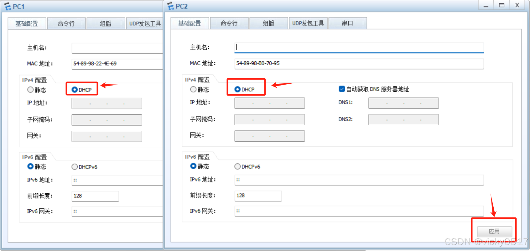
?
?
三、配置靜態明細路由,內網全網通?
R1-R5配置如下:
[R1]ip route-static 192.168.1.64 27 192.168.1.2
[R1]ip route-static 192.168.1.8 30 192.168.1.2
[R1]ip route-static 192.168.1.128 27 192.168.1.2
[R1]ip route-static 192.168.1.128 27 192.168.1.6
[R1]ip route-static 192.168.1.16 30 192.168.1.6
[R1]ip route-static 192.168.1.16 30 192.168.1.2
[R1]ip route-static 192.168.1.20 30 192.168.1.2
[R1]ip route-static 192.168.1.20 30 192.168.1.6
[R1]ip route-static 192.168.1.160 27 192.168.1.6
[R1]ip route-static 192.168.1.160 27 192.168.1.2
[R1]ip route-static 192.168.1.12 30 192.168.1.6
[R1]ip route-static 192.168.1.96 27 192.168.1.6
[R2]ip route-static 192.168.1.128 27 192.168.1.10
[R2]ip route-static 192.168.1.16 30 192.168.1.10
[R2]ip route-static 192.168.1.20 30 192.168.1.10
[R2]ip route-static 192.168.1.160 27 192.168.1.10
[R2]ip route-static 192.168.1.12 30 192.168.1.10
[R2]ip route-static 192.168.1.96 27 192.168.1.10
[R2]ip route-static 192.168.1.96 27 192.168.1.1
[R2]ip route-static 192.168.1.4 30 192.168.1.1
[R2]ip route-static 192.168.1.32 27 192.168.1.1[R3]ip route-static 192.168.1.32 27 192.168.1.5
[R3]ip route-static 192.168.1.0 30 192.168.1.5
[R3]ip route-static 192.168.1.64 27 192.168.1.5
[R3]ip route-static 192.168.1.64 27 192.168.1.14
[R3]ip route-static 192.168.1.8 30 192.168.1.14
[R3]ip route-static 192.168.1.128 27 192.168.1.14
[R3]ip route-static 192.168.1.16 30 192.168.1.14
[R3]ip route-static 192.168.1.20 30 192.168.1.14
[R3]ip route-static 192.168.1.160 27 192.168.1.14[R4]ip route-static 192.168.1.96 27 192.168.1.13
[R4]ip route-static 192.168.1.4 30 192.168.1.13
[R4]ip route-static 192.168.1.32 27 192.168.1.13
[R4]ip route-static 192.168.1.32 27 192.168.1.9
[R4]ip route-static 192.168.1.0 30 192.168.1.9
[R4]ip route-static 192.168.1.64 27 192.168.1.9
[R4]ip route-static 192.168.1.160 27 192.168.1.18
[R4]ip route-static 192.168.1.160 27 192.168.1.22[R5]ip route-static 192.168.1.128 27 192.168.1.17
[R5]ip route-static 192.168.1.128 27 192.168.1.21
[R5]ip route-static 192.168.1.12 30 192.168.1.21
[R5]ip route-static 192.168.1.12 30 192.168.1.17
[R5]ip route-static 192.168.1.96 27 192.168.1.17
[R5]ip route-static 192.168.1.96 27 192.168.1.21
[R5]ip route-static 192.168.1.4 30 192.168.1.21
[R5]ip route-static 192.168.1.4 30 192.168.1.17
[R5]ip route-static 192.168.1.32 27 192.168.1.17
[R5]ip route-static 192.168.1.32 27 192.168.1.21
[R5]ip route-static 192.168.1.0 30 192.168.1.21
[R5]ip route-static 192.168.1.0 30 192.168.1.17
[R5]ip route-static 192.168.1.64 27 192.168.1.17
[R5]ip route-static 192.168.1.64 27 192.168.1.21
[R5]ip route-static 192.168.1.8 30 192.168.1.21
[R5]ip route-static 192.168.1.8 30 192.168.1.17?內網全網通測試(用R1去ping通R5的環回):
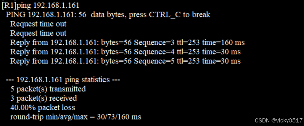
可以ping通,至此,內外全網通了。
四、配置空接口防環
?由于R1、R2、R4進行了路由匯總,則可能會會出現路由黑洞和環路,需要配置空接口進行防環。
[R1]ip route-static 192.168.1.32 27 NULL 0
[R2]ip route-static 192.168.1.64 27 NULL 0
[R4]ip route-static 192.168.1.128 27 NULL 0
五、配置優先級,實現選路最佳
在R4與R5直接有兩條直連鏈路,分別是1000M與100M,我們需要配置兩條鏈路的優先級,來實現當1000M鏈路出現故障時,路由會自動選擇100M鏈路進行數據傳輸。配置如下:
[R4]dis ip routing-table protocol static 目標IP/掩碼       協議  優先級 花銷  標志      下一跳               接口
Destination/Mask Proto  Pre  Cost  Flags     NextHop           Interface
192.168.1.0/30   Static  60   0    RD     192.168.1.9    GigabitEthernet0/0/0
192.168.1.4/30   Static  60   0    RD     192.168.1.13   GigabitEthernet0/0/1
192.168.1.32/27  Static  60   0    RD     192.168.1.13   GigabitEthernet0/0/1Static  60   0    RD     192.168.1.9    GigabitEthernet0/0/0
192.168.1.64/27  Static  60   0    RD     192.168.1.9    GigabitEthernet0/0/0
192.168.1.96/27  Static  60   0    RD     192.168.1.13   GigabitEthernet0/0/1
192.168.1.128/27 Static  60   0    D      0.0.0.0        NULL0
192.168.1.160/27 Static  60   0    RD     192.168.1.18   GigabitEthernet4/0/0Static  60   0    RD     192.168.1.22
通過查看R4的靜態路由協議可以看出,只有去往192.168.1.160/27的下一跳為192.168.1.22,該接口在100M的鏈路上。我們只需修改該路由條目的靜態優先級為61即可。?
[R4]ip route-static 192.168.1.160 27 192.168.1.22 preference 61
只修改R4上路由的優先級還不夠,還需將直連R5的路由優先級修改,才可實現最路最佳。
查看R5 的靜態路由協議可以看出,R5去往R1、R2、R3、R4的下一跳均為192.168.1.21,該接口也在100M的鏈路上。
[R5]dis ip routing-table protocol static 目的IP/掩碼        協議  優先級 花銷 標志      下一跳                接口
Destination/Mask Proto   Pre  Cost Flags   NextHop             Interface192.168.1.0/30   Static  60   0   RD    192.168.1.21    GigabitEthernet0/0/0Static  60   0   RD    192.168.1.17    GigabitEthernet0/0/1
192.168.1.4/30   Static  60   0   RD    192.168.1.21    GigabitEthernet0/0/0Static  60   0   RD    192.168.1.17    GigabitEthernet0/0/1
192.168.1.8/30   Static  60   0   RD    192.168.1.21    GigabitEthernet0/0/0Static  60   0   RD    192.168.1.17    GigabitEthernet0/0/1
192.168.1.12/30  Static  60   0   RD    192.168.1.21    GigabitEthernet0/0/0Static  60   0   RD    192.168.1.17    GigabitEthernet0/0/1
192.168.1.32/27  Static  60   0   RD    192.168.1.17    GigabitEthernet0/0/1Static  60   0   RD    192.168.1.21    GigabitEthernet0/0/0
192.168.1.64/27  Static  60   0   RD    192.168.1.17    GigabitEthernet0/0/1Static  60   0   RD    192.168.1.21    GigabitEthernet0/0/0
192.168.1.96/27  Static  60   0   RD    192.168.1.17    GigabitEthernet0/0/1Static  60   0   RD    192.168.1.21    GigabitEthernet0/0/0
192.168.1.128/27 Static  60   0   RD    192.168.1.17    GigabitEthernet0/0/1Static  60   0   RD    192.168.1.21    GigabitEthernet0/0/0
?所以,R5配置如下:
[R5]ip route-static 192.168.1.128 27 192.168.1.21 pre 61
[R5]ip route-static 192.168.1.12 30 192.168.1.21 pre 61
[R5]ip route-static 192.168.1.96 27 192.168.1.21 pre 61
[R5]ip route-static 192.168.1.4 30 192.168.1.21 pre 61
[R5]ip route-static 192.168.1.32 27 192.168.1.21 pre 61
[R5]ip route-static 192.168.1.0 30 192.168.1.21 pre 61
[R5]ip route-static 192.168.1.64 27 192.168.1.21 pre 61
[R5]ip route-static 192.168.1.8 30 192.168.1.21 pre 61
關閉1000M鏈路的接口進行測試如下:
[R4]int g4/0/0
[R4-GigabitEthernet4/0/0]shutdown
?
#關閉前,跟蹤從R1去往R5環回的路徑如下
[R1]tracert 192.168.1.161traceroute to  192.168.1.161(192.168.1.161), max hops: 30 ,packet length: 40,pr
ess CTRL_C to break 1 192.168.1.6 50 ms  20 ms 192.168.1.2 120 ms 2  * 192.168.1.10 70 ms  30 ms 3 192.168.1.18 50 ms  30 ms  30 ms
##關閉后路徑跟蹤如下:
[R1]tracert 192.168.1.161traceroute to  192.168.1.161(192.168.1.161), max hops: 30 ,packet length: 40,pr
ess CTRL_C to break 1 192.168.1.6 40 ms  20 ms 192.168.1.2 20 ms 2 192.168.1.10 30 ms  20 ms  10 ms 3 192.168.1.22 40 ms  30 ms  30 ms
清楚的看出,關閉前路由走的是192.168.1.18的1000M鏈路,關閉1000M接口后,路由選擇走的是192.168.1.22的100M鏈路。至此,實現了選錄最佳。
六、配置缺省路由,實現公網通
要是內網可以訪問公網,則需要在R1-R5上配置去往公網ISP的路由,但R1-R4并不知道去往ISP的IP,這就需要進行缺省配置了。
R1-R5的缺省配置如下:
[R1]ip route-static 0.0.0.0 0 192.168.1.2
[R1]ip route-static 0.0.0.0 0 192.168.1.6[R2]ip route-static 0.0.0.0 0 192.168.1.10[R3]ip route-static 0.0.0.0 0 192.168.1.14[R4]ip route-static 0.0.0.0 0 192.168.1.18
[R4]ip route-static 0.0.0.0 0 192.168.1.22
[R4]ip route-static 0.0.0.0 0 192.168.1.22 pre 61[R5]ip route-static 0.0.0.0 0 12.0.0.2
七、配置nat配置內網訪問公網
?R5作為內網去往ISP的邊界路由,我們需要在R5上進行NAT配置,實現公網ip地址和私網ip地址之間的相互轉換,且華為設備所有NAT相關的配置都是在邊界路由器的出接口上配置,該端口轉換屬于PAT一對多類型,也就是easy ip配置。
1...通過ACL抓取私網流量,配置如下:
[R5]acl 2000
[R5-acl-basic-2000]rule permit source 192.168.1.0 0.0.0.255
2... 在出接口上配置
[R5]int g0/0/2
[R5-GigabitEthernet0/0/2]nat outbound 2000
3...端口映射
[R5]int g0/0/2
[R5-GigabitEthernet0/0/2]nat server protocol tcp global current-interface 23 inside 192.168.1.1 23
Warning:The port 23 is well-known port. If you continue it may cause function failure.
Are you sure to continue?[Y/N]:yes
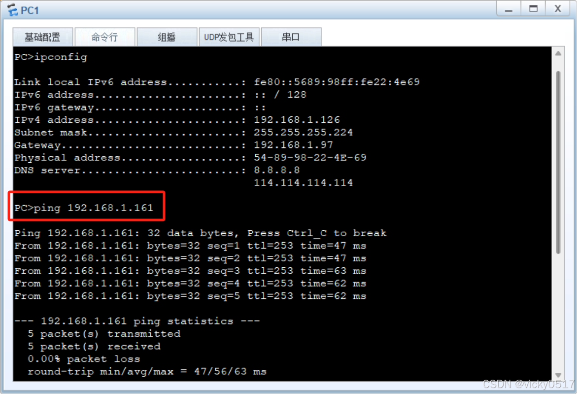
[R5-GigabitEthernet0/0/2]q用pc1去訪問ISP的環回:

?可以ping通。
八、做NAT SERVER,發布內網服務器服務
實驗要求R6 telnet R5的公有地址時,實際登錄到R1上,則我們需要在R1上做telnet服務。
配置如下:
[R1]telnet server enable
[R1]aaa
[R1-aaa]local-user  vicky password cipher 111111 privilege level 15
[R1-aaa]local-user vicky service-type telnet
[R1-aaa]q
[R1]user-interface vty  0 4
[R1-ui-vty0-4]authentication-mode aaa
[R1-ui-vty0-4]q
在R6上telnetR5如下:

成功登錄R1。
至此,所有實驗要求都完成了。
Hive聚合函數深度解析:從基礎統計到多維聚合的12個生產級技巧)


用于執行兩個矩陣(或圖像)逐元素乘法操作的函數mul())


)

