上一章完成了相機類的實現,對之前所學的內容進行了封裝與整理,現在要學習新的內容。
抗鋸齒
我們放大之前渲染的圖片,往往會發現我們渲染的圖像邊緣有尖銳的"階梯"性質。這種階梯狀被稱為"鋸齒"。當真實的相機拍照時,邊緣通常沒有鋸齒,這是因為真實的邊緣時前景和背景顏色的混合,而不是簡單的二值化。而且真實的世界是連續的,而我們渲染的圖像是離散的,也就是說真實世界具有無限的分辨率 ,而我們的=圖像的分辨率是有限的。我們可以通過對每個像素進行多次采樣并取平均值,來近似實現此效果。
我們目前采用的采樣方式被稱為”點采樣“,即在每個像素的中心發射一條射線來進行采樣,但是同時也面臨一個問題,當我們對較遠的地方的圖像進行采樣時,可能會出現"非黑即白"的情況。但實際上我們應該看到的是灰色,而不是黑白分明的點。這是我們的眼睛很自然的對遠處的圖形進行了處理,而這種處理正是我們想要的效果。
所以為了解決這個問題,我們采用"多采樣"的方式,來對我們的圖片實現采樣。我們需要對像素周圍的光線進行采樣,然后對采樣的結果進行整合,以近似真實世界的連續效果。
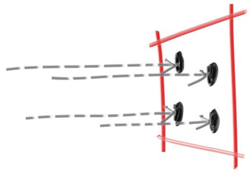
為了實現這種效果,我們采用最為簡單的方式,我們對以像素為中心的正方形區域進行采樣,這個正方形區域會延伸到每個相鄰的像素的一般位置。這個方法可能效果一般,但是便于實現,具體的內容可以參考文獻像素不是一個小方塊,下面是一個多采樣草圖
數學工具:隨機數生成
為了實現函數的多采樣,我們需要一個能夠返回真實隨機數的隨機數生成器。這個函數為我們返回一個(0,1)的隨機數,我們可以使用標準庫<cstdlib>中的std::rand()函數,這個函數會返回一個[0,RAND_MAX]之間的隨機整數。我們通過以下改動,可以得到真正的隨機數函數,我們寫在rtweekend.h中:
#include <cmath>
#include <cstdlib>
#include <iostream>
#include <limits>
#include <memory>
...
//實用函數
inline double degree_to_radius(double degrees){return degrees * pi / 180.0;
}
inline double random_double(){//返回[0,1)的數return std::rand() / (RAND_MAX + 1.0);
}
inline double random_double(double min,double max){//返回[min,max)的數return min + (max - min)*random_double();
}
不過由于rand()具有隨機性較差等特點,所以在C++11標準下有其他的隨機數函數寫法:
...
#include <random>
...
inline double random_double(){static std::uniform_real_distribution<double> distribution(0.0,1.0);static std::mt19937 generator;return distribution(generator);
}
...
不過看不太懂就是了
使用多采樣式生成像素
對于由多個樣本組成的像素,我們將從像素周圍的區域選擇樣本,并將顏色(光值)平均在一起
我們需要更新我們的write_color()函數以考慮我們的樣本數量,不過在此之前,我們需要添加一個用于區間判斷的輔助函數interval::clamp(x),以確保最終的結果的顏色分量保持在正確的[0,1]范圍:
class interval{
public:
...
//包含double clamp(double x) const{if(x < min) return min;if(x > max) return max;return x;}
接下來我們更新write_color()函數,其包含區間的限制功能:
 ?void write_color(std::ostream& out,const color& pixel_color){auto r = pixel_color.x();auto g = pixel_color.y();auto b = pixel_color.z();//使用區間RGB[0,1]計算RGB值static const interval intensity(0.000,0.999);int rbyte = int (256*intensity.clamp(r));int gbyte = int (256*intensity.clamp(g));int bbyte = int (256*intensity.clamp(b));out << rbyte << ' ' << gbyte << ' ' << bbyte << '\n';
}
這樣保證了我們的的rgb分量不會超出[0,1]的范圍,這樣更加安全。
接下來我們需要更新相機類,以定義和使用一個新的camera::get_ray(i,j)函數,該函數將為每個像素生成不同的樣本。這個函數將使用一個新的輔助函數sample_squred(),該函數在以原點為中心的正方形內生成一個隨機樣本點。然后我們將這個正方形中的隨機樣本轉換為我們當前正在采樣的特定像素。
?
#ifndef RENDER_C___CAMERA_H
#define RENDER_C___CAMERA_H
?
#include "hittable.h"
?
class camera{
public:double aspect_radio = 1.0; ? ? ?//圖像的寬高比int ? ?image_width = 100; ? ? ? //圖像寬度的像素數int ? ?samples_per_pixel = 10; ?//每個像素的采樣次數
?void render(const hittable& world){initialize();
?std::cout << "P3\n" << image_width << " " << image_height << "\n255\n";for(int j=0;j<image_height;j++){std::clog << "\rScanlines remaining: " << (image_height - j) << ' ' << std::flush;for(int i=0;i<image_width;i++){color pixel_color(0,0,0);for(int sample = 0;sample < samples_per_pixel; sample++){ray r = get_ray(i,j);pixel_color += ray_color(r,world);}write_color(std::cout,pixel_color*pixel_samples_scale);}}std::clog << "\rDone. ? ? ? ? ? ? ? ? ? \n";}
?
private:int image_height; ? ? ? ? ? //渲染圖像的高度double pixel_samples_scale; //每次采樣的顏色權重point3 camera_center; ? ? ? //相機的中心point3 pixel00_loc; ? ? ? ? //像素(0,0)的位置vec3 pixel_delta_u; ? ? ? ? //向右的偏移值vec3 pixel_delta_v; ? ? ? ? //向下的偏移值
?void initialize(){image_height = int(image_width/aspect_radio);image_height = (image_height < 1) ? 1 : image_height;
?pixel_samples_scale = 1.0 / samples_per_pixel;
?camera_center = point3 (0,0,0);
?//確認視窗的設置auto focal_length = 1.0; ? ?//焦距設置auto viewport_height = 2.0;auto viewport_width = viewport_height*(double (image_width)/image_height);
?//視圖邊緣的向量計算auto viewport_u = vec3(viewport_width,0,0);auto viewport_v = vec3(0,-viewport_height,0);//計算視圖的像素間的水平豎直增量pixel_delta_u = viewport_u/image_width;pixel_delta_v = viewport_v/image_height;
?//計算左上角第一個像素中心的坐標auto viewport_upper_left = camera_center - vec3(0,0,focal_length) - viewport_v/2 - viewport_u/2;pixel00_loc = viewport_upper_left + 0.5*(pixel_delta_u+pixel_delta_v);}
?ray get_ray(int i,int j){//構造一個從原點開始的隨機采樣射線,指向(i,j)像素
?auto offset = sample_square();auto pixel_sample = pixel00_loc + ((i+offset.x())*pixel_delta_u) + ((j+offset.y())*pixel_delta_v);
?auto ray_origin = camera_center;auto ray_direction = pixel_sample - ray_origin;
?return ray(ray_origin,ray_direction);}
?vec3 sample_square() const {//返回一個一個隨機的點,在[-0.5,-0.5]~[+0.5,+0.5]的單位矩陣內return {random_double() - 0.5, random_double() - 0.5,0};}
?color ray_color(ray & r,const hittable& world){hit_record rec;if(world.hit(r,interval(0,infinity),rec)){return 0.5*(rec.normal + color(1,1,1));}
?vec3 unit_direction = unit_vector(r.direction());auto a = 0.5*(unit_direction.y()+1.0);return (1.0 - a)*color(1.0,1.0,1.0) + a*color(0.5,0.7,1.0);}
};
?
#endif //RENDER_C___CAMERA_H
這是新的camera,我們更新了get_ray()和sample_square(),還有新的公有私有屬性
接下來設置一下主函數的參數:
?
int main(){hittable_list world;world.add(make_shared<sphere>(point3(0,0,-1),0.5));world.add(make_shared<sphere>(point3(0,-100.5,-1),100));
?camera cam;
?cam.aspect_radio = 16.0/9.0;cam.image_width = 400;cam.samples_per_pixel = 100;    // 設置采樣次數
?cam.render(world);
}
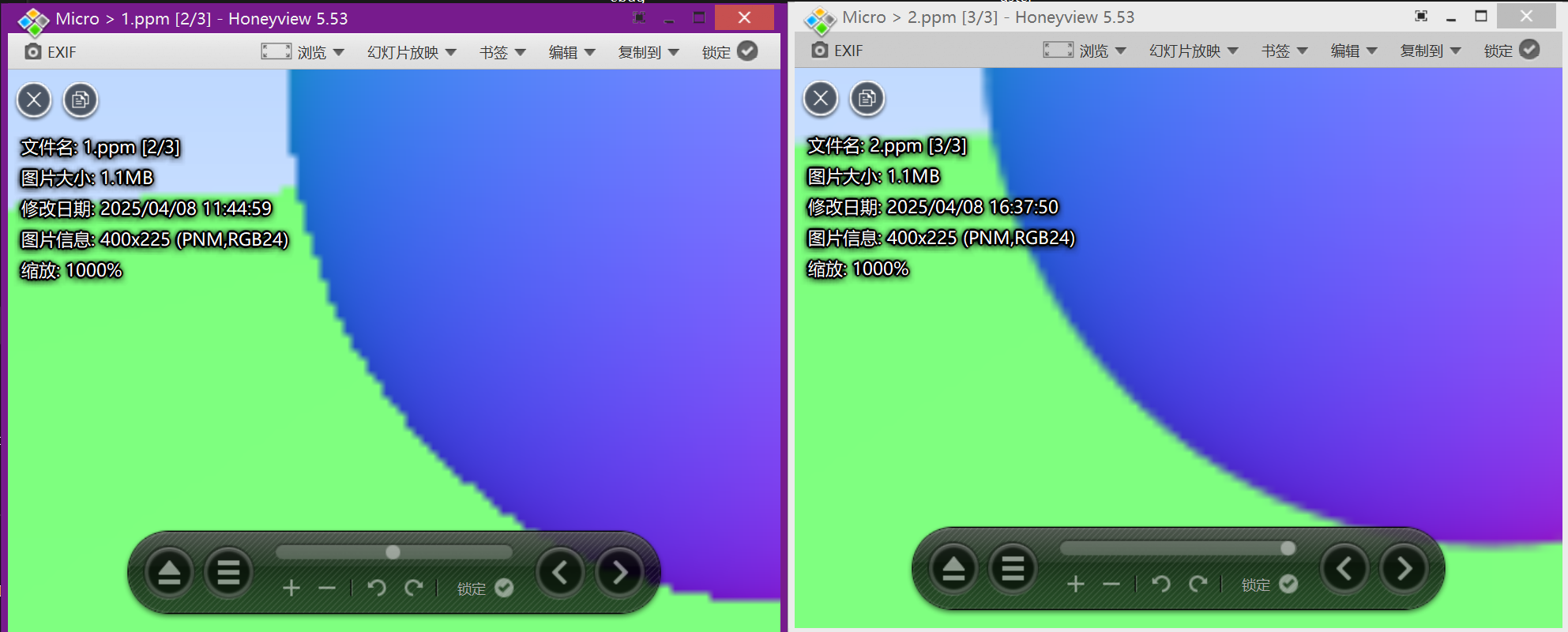
這里可以看到左圖的鋸齒明顯減少了,我們的抗鋸齒設置的十分成功,今天就到此為止了


)
)

)


)


