注:本文為 “Linux PCI Drivers” 相關文章合輯。
英文引文,機翻未校。
中文引文,略作重排。
如有內容異常,請看原文。
How To Write Linux PCI Drivers
翻譯:
司延騰 Yanteng Si siyanteng@loongson.cn
1. 如何寫 Linux PCI 驅動
- 作者:
- Martin Mares <mj@ucw.cz>
- Grant Grundler <grundler@parisc-linux.org>
PCI 的世界是巨大的,而且充滿了(大多數是不愉快的)驚喜。由于每個 CPU 架構實現了不同的芯片組,并且 PCI 設備有不同的要求(呃,“特性”),結果是 Linux 內核中的 PCI 支持并不像人們希望的那樣簡單。這篇短文試圖向所有潛在的驅動程序作者介紹 Linux APIs 中的 PCI 設備驅動程序。
更完整的資源是 Jonathan Corbet、Alessandro Rubini 和 Greg Kroah-Hartman 的《Linux 設備驅動程序》第三版。LDD3 可以免費獲得(在知識共享許可下),網址是:Linux Device Drivers, Third Edition。
然而,請記住,所有的文檔都會受到“維護不及時”的影響。如果事情沒有按照這里描述的那樣進行,請參考源代碼。
請將有關 Linux PCI API 的問題/評論/補丁發送到“Linux PCI”<linux-pci@atrey.karlin.mff.cuni.cz>郵件列表。
1.1. PCI 驅動的結構體
PCI 驅動通過 pci_register_driver() 在系統中“發現”PCI 設備。實際上,它是反過來的。當 PCI 通用代碼發現一個新設備時,具有匹配“描述”的驅動程序將被通知。下面是這方面的細節。
pci_register_driver() 將大部分探測設備的工作留給了 PCI 層,并支持設備的在線插入/移除(從而在一個驅動中支持可熱插拔的 PCI、CardBus 和 Express-Card)。pci_register_driver() 調用需要傳入一個函數指針表,從而決定了驅動的高層結構體。
一旦驅動探測到一個 PCI 設備并取得了所有權,驅動通常需要執行以下初始化:
- 啟用設備
- 請求 MMIO/IOP 資源
- 設置 DMA 掩碼大小(對于流式和一致的 DMA)
- 分配和初始化共享控制數據(
pci_allocate_coherent()) - 訪問設備配置空間(如果需要)
- 注冊 IRQ 處理程序(
request_irq()) - 初始化非 PCI(即芯片的 LAN/SCSI/ 等部分)
- 啟用 DMA/處理引擎
當使用完設備后,也許需要卸載模塊,驅動需要采取以下步驟:
- 禁用設備產生的 IRQ
- 釋放 IRQ(
free_irq()) - 停止所有 DMA 活動
- 釋放 DMA 緩沖區(包括一致性和數據流式)
- 從其他子系統(例如 scsi 或 netdev)上取消注冊
- 釋放 MMIO/IOP 資源
- 禁用設備
這些主題中的大部分都在下面的章節中有所涉及。其余的內容請參考 LDD3 或 <linux/pci.h>。
如果沒有配置 PCI 子系統(沒有設置 CONFIG_PCI),下面描述的大多數 PCI 函數被定義為內聯函數,要么完全為空,要么只是返回一個適當的錯誤代碼,以避免在驅動程序中出現大量的 ifdef。
1.2. 調用 pci_register_driver()
PCI 設備驅動程序在初始化過程中調用 pci_register_driver(),并提供一個指向描述驅動程序的結構體的指針(struct pci_driver):
struct pci_driver {const char              *name;const struct pci_device_id *id_table;int (*probe)(struct pci_dev *dev, const struct pci_device_id *id);void (*remove)(struct pci_dev *dev);int (*suspend)(struct pci_dev *dev, pm_message_t state);int (*resume)(struct pci_dev *dev);void (*shutdown)(struct pci_dev *dev);int (*sriov_configure)(struct pci_dev *dev, int num_vfs);int (*sriov_set_msix_vec_count)(struct pci_dev *vf, int msix_vec_count);u32 (*sriov_get_vf_total_msix)(struct pci_dev *pf);const struct pci_error_handlers *err_handler;const struct attribute_group **groups;const struct attribute_group **dev_groups;struct device_driver    driver;struct pci_dynids       dynids;bool driver_managed_dma;
};
成員
name:驅動程序名稱。id_table:指向設備 ID 表的指針,驅動程序感興趣的設備 ID 表。大多數驅動程序應該導出此表,使用MODULE_DEVICE_TABLE(pci,...)。probe:當發現匹配 ID 表且尚未被其他驅動程序“擁有”的 PCI 設備時,此探測函數會被調用(在執行pci_register_driver()時用于已存在的設備,或者在插入新設備時)。此函數會傳遞一個struct pci_dev *,用于每個匹配設備表條目的設備。如果驅動程序選擇“擁有”該設備,則返回零;否則返回錯誤代碼(負數)。remove:當處理該驅動程序的設備被移除時(無論是注銷驅動程序還是手動從熱插拔插槽中拔出設備),此函數會被調用。suspend:將設備置于低功耗狀態。resume:喚醒處于低功耗狀態的設備。shutdown:在重啟通知列表(kernel/sys.c)中注冊。用于停止任何空閑的 DMA 操作。sriov_configure:可選的驅動程序回調,允許通過 sysfs 文件“sriov_numvfs”配置虛擬功能(VF)的數量。sriov_set_msix_vec_count:PF 驅動程序回調,用于更改 VF 的 MSI-X 向量數量。通過 sysfs 文件“sriov_vf_msix_count”觸發。這將更改 VF 消息控制寄存器中的 MSI-X 表大小。sriov_get_vf_total_msix:PF 驅動程序回調,用于獲取可分配給 VF 的 MSI-X 向量總數。err_handler:參見 PCI 錯誤恢復。groups:Sysfs 屬性組。dev_groups:附加到設備的屬性,將在設備綁定到驅動程序后創建。driver:驅動程序模型結構體。dynids:動態添加的設備 ID 列表。driver_managed_dma:設備驅動程序不使用內核 DMA API 進行 DMA。對于大多數設備驅動程序,無需關心此標志,只要所有 DMA 都通過內核 DMA API 處理即可。對于一些特殊驅動程序(例如 VFIO 驅動程序),它們知道如何管理自己的 DMA,因此設置此標志,以便 IOMMU 層允許它們設置和管理自己的 I/O 地址空間。
ID 表是一個由 struct pci_device_id 結構體成員組成的數組,以一個全零的成員結束。一般來說,帶有靜態常數的定義是首選。
struct pci_device_id {__u32 vendor, device;__u32 subvendor, subdevice;__u32 class, class_mask;kernel_ulong_t driver_data;__u32 override_only;
};
成員
vendor:要匹配的供應商 ID(或PCI_ANY_ID)。device:要匹配的設備 ID(或PCI_ANY_ID)。subvendor:要匹配的子系統供應商 ID(或PCI_ANY_ID)。subdevice:要匹配的子系統設備 ID(或PCI_ANY_ID)。class:要匹配的設備類別、子類別和“接口”。class_mask:限制類別字段中要比較的子字段。driver_data:私有驅動程序數據。大多數驅動程序不需要使用driver_data字段。最佳實踐是將driver_data用作靜態列表中等效設備類型的索引,而不是用作指針。override_only:僅當dev->driver_override是此驅動程序時才匹配。
大多數驅動程序只需要 PCI_DEVICE() 或 PCI_DEVICE_CLASS() 來設置一個 pci_device_id 表。
新的 PCI ID 可以在運行時被添加到設備驅動的 pci_ids 表中,如下所示:
echo "vendor device subvendor subdevice class class_mask driver_data" > \
/sys/bus/pci/drivers/{driver}/new_id
所有字段都以十六進制值傳遞(沒有前置 0x)。供應商和設備字段是強制性的,其他字段是可選的。用戶只需要傳遞必要的可選字段:
subvendor和subdevice字段默認為PCI_ANY_ID(FFFFFFFF)。class和classmask字段默認為0。driver_data默認為0UL。override_only字段默認為0。
請注意,driver_data 必須與驅動程序中定義的任何一個 pci_device_id 條目所使用的值相匹配。如果所有的 pci_device_id 成員都有一個非零的 driver_data 值,這使得 driver_data 字段是強制性的。
一旦添加,驅動程序探測程序將被調用,以探測其(新更新的)pci_ids 列表中列出的任何無人認領的 PCI 設備。
當驅動退出時,它只是調用 pci_unregister_driver(),PCI 層會自動調用驅動處理的所有設備的移除鉤子。
1.2.1. 驅動程序功能/數據的“屬性”
請在適當的地方標記初始化和清理函數(相應的宏在 <linux/init.h> 中定義):
| 屬性 | 描述 |
|---|---|
__init | 初始化代碼。在驅動程序初始化后被拋棄。 |
__exit | 退出代碼。對于非模塊化的驅動程序來說是忽略的。 |
關于何時/何地使用上述屬性的提示:
module_init()和module_exit()函數(以及所有僅由這些函數調用的初始化函數)應該被標記為__init/__exit。- 不要標記
struct pci_driver結構體。 - 如果你不確定應該使用哪種標記,請不要標記一個函數。不標記函數比標記錯誤的函數更好。
1.3. 如何手動搜索 PCI 設備
PCI 驅動最好有一個非常好的理由不使用 pci_register_driver() 接口來搜索 PCI 設備。PCI 設備被多個驅動程序控制的主要原因是一個 PCI 設備實現了幾個不同的 HW 服務。例如,組合的串行/并行端口/軟盤控制器。
可以使用以下結構體進行手動搜索:
通過供應商和設備 ID 進行搜索:
struct pci_dev *dev = NULL;
while (dev = pci_get_device(VENDOR_ID, DEVICE_ID, dev))configure_device(dev);
按類別 ID 搜索(以類似的方式迭代):
pci_get_class(CLASS_ID, dev)
通過供應商/設備和子系統供應商/設備 ID 進行搜索:
pci_get_subsys(VENDOR_ID, DEVICE_ID, SUBSYS_VENDOR_ID, SUBSYS_DEVICE_ID, dev).
你可以使用常數 PCI_ANY_ID 作為 VENDOR_ID 或 DEVICE_ID 的通配符替代。例如,這允許搜索來自一個特定供應商的任何設備。
這些函數是熱拔插安全的。它們會增加它們所返回的 pci_dev 的參考計數。你最終必須通過調用 pci_dev_put() 來減少這些設備上的參考計數(可能在模塊卸載時)。
1.4. 設備初始化步驟
正如介紹中所指出的,大多數 PCI 驅動需要以下步驟進行設備初始化:
- 啟用設備
- 請求 MMIO/IOP 資源
- 設置 DMA 掩碼大小(對于流式和一致的 DMA)
- 分配和初始化共享控制數據(
pci_allocate_coherent()) - 訪問設備配置空間(如果需要)
- 注冊 IRQ 處理程序(
request_irq()) - 初始化非 PCI(即芯片的 LAN/SCSI/ 等部分)
- 啟用 DMA/處理引擎
驅動程序可以在任何時候訪問 PCI 配置空間寄存器。(嗯,幾乎如此。當運行 BIST 時,配置空間可以消失……但這只會導致 PCI 總線主控中止,讀取配置將返回垃圾值。)
1.4.1. 啟用 PCI 設備
在接觸任何設備寄存器之前,驅動程序需要通過調用 pci_enable_device() 啟用 PCI 設備。這將:
- 喚醒處于暫停狀態的設備。
- 分配設備的 I/O 和內存區域(如果 BIOS 沒有這樣做)。
- 分配一個 IRQ(如果 BIOS 沒有)。
注意:pci_enable_device() 可能失敗,檢查返回值。
警告:OS BUG:在啟用這些資源之前,我們沒有檢查資源分配情況。如果我們在調用 pci_request_resources() 之前調用 pci_enable_device(),這個順序會更合理。目前,當兩個設備被分配了相同的范圍時,設備驅動無法檢測到這個錯誤。這不是一個常見的問題,不太可能很快得到修復。
這個問題之前已經討論過了,但從 2.6.19 開始沒有改變:
https://lore.kernel.org/r/20060302180025.GC28895@flint.arm.linux.org.uk/
pci_set_master() 將通過設置 PCI_COMMAND 寄存器中的總線主控位來啟用 DMA。pci_clear_master() 將通過清除總線主控位來禁用 DMA,它還修復了延遲計時器的值,如果它被 BIOS 設置成假的。
如果 PCI 設備可以使用 PCI Memory-Write-Invalidate 事務,請調用 pci_set_mwi()。這將啟用 Mem-Wr-Inval 的 PCI_COMMAND 位,也確保緩存行大小寄存器被正確設置。檢查 pci_set_mwi() 的返回值,因為不是所有的架構或芯片組都支持 Memory-Write-Invalidate。另外,如果 Mem-Wr-Inval 是好的,但不是必須的,可以調用 pci_try_set_mwi(),讓系統盡最大努力來啟用 Mem-Wr-Inval。
1.4.2. 請求 MMIO/IOP 資源
內存(MMIO)和 I/O 端口地址不應該直接從 PCI 設備配置空間中讀取。使用 pci_dev 結構體中的值,因為 PCI“總線地址”可能已經被 arch/chip-set 特定的內核支持重新映射為“主機物理”地址。
參見 io_mapping 函數,了解如何訪問設備寄存器或設備內存。
設備驅動需要調用 pci_request_region() 來確認沒有其他設備已經在使用相同的地址資源。反之,驅動應該在調用 pci_disable_device() 之后調用 pci_release_region()。這個想法是為了防止兩個設備在同一地址范圍內發生沖突。
提示:見上面的操作系統 BUG 注釋。目前(2.6.19),驅動程序只能在調用 pci_enable_device() 后確定 MMIO 和 IO 端口資源的可用性。
pci_request_region() 的通用風格是 request_mem_region()(用于 MMIO 范圍)和 request_region()(用于 IO 端口范圍)。對于那些不被“正常”PCI BAR 描述的地址資源,使用這些方法。
也請看下面的 pci_request_selected_regions()。
1.4.3. 設置 DMA 掩碼大小
注意:如果下面有什么不明白的地方,請參考使用通用設備的動態 DMA 映射。本節只是提醒大家,驅動程序需要說明設備的 DMA 功能,并不是 DMA 接口的權威來源。
雖然所有的驅動程序都應該明確指出 PCI 總線主控的 DMA 功能(如 32 位或 64 位),但對于流式數據來說,具有超過 32 位總線主站功能的設備需要驅動程序通過調用帶有適當參數的 dma_set_mask() 來“注冊”這種功能。一般來說,在系統 RAM 高于 4G 物理地址的情況下,這允許更有效的 DMA。
所有 PCI-X 和 PCIe 兼容設備的驅動程序必須調用 dma_set_mask(),因為它們是 64 位 DMA 設備。
同樣,如果設備可以通過調用 dma_set_coherent_mask() 直接尋址到 4G 物理地址以上的系統 RAM 中的“一致性內存”,那么驅動程序也必須“注冊”這種功能。同樣,這包括所有 PCI-X 和 PCIe 兼容設備的驅動程序。許多 64 位“PCI”設備(在 PCI-X 之前)和一些 PCI-X 設備對有效載荷(“流式”)數據具有 64 位 DMA 功能,但對控制(“一致性”)數據則沒有。
1.4.4. 設置共享控制數據
一旦 DMA 掩碼設置完畢,驅動程序就可以分配“一致的”(又稱共享的)內存。參見使用通用設備的動態 DMA 映射,了解 DMA API 的完整描述。本節只是提醒大家,需要在設備上啟用 DMA 之前完成。
1.4.5. 初始化設備寄存器
一些驅動程序需要對特定的“功能”字段進行編程,或對其他“供應商專用”寄存器進行初始化或重置。例如,清除掛起的中斷。
1.4.6. 注冊 IRQ 處理函數
雖然調用 request_irq() 是這里描述的最后一步,但這往往只是初始化設備的另一個中間步驟。這一步通常可以推遲到設備被打開使用時進行。
所有 IRQ 線的中斷處理程序都應該用 IRQF_SHARED 注冊,并使用 devid 將 IRQ 映射到設備(記住,所有的 PCI IRQ 線都可以共享)。
request_irq() 將把一個中斷處理程序和設備句柄與一個中斷號聯系起來。歷史上,中斷號碼代表從 PCI 設備到中斷控制器的 IRQ 線。在 MSI 和 MSI-X 中(更多內容見下文),中斷號是 CPU 的一個“向量”。
request_irq() 也啟用中斷。在注冊中斷處理程序之前,請確保設備是靜止的,并且沒有任何中斷等待。
MSI 和 MSI-X 是 PCI 功能。兩者都是“消息信號中斷”,通過向本地 APIC 的 DMA 寫入來向 CPU 發送中斷。MSI 和 MSI-X 的根本區別在于如何分配多個“向量”。MSI 需要連續的向量塊,而 MSI-X 可以分配幾個單獨的向量。
在調用 request_irq() 之前,可以通過調用 pci_alloc_irq_vectors() 的 PCI_IRQ_MSI 和/或 PCI_IRQ_MSIX 標志來啟用 MSI 功能。這將導致 PCI 支持將 CPU 向量數據編程到 PCI 設備功能寄存器中。許多架構、芯片組或 BIOS 不支持 MSI 或 MSI-X,調用 pci_alloc_irq_vectors 時只使用 PCI_IRQ_MSI 和 PCI_IRQ_MSIX 標志會失敗,所以盡量也要指定 PCI_IRQ_INTX。
對 MSI/MSI-X 和傳統 INTx 有不同中斷處理程序的驅動程序應該在調用 pci_alloc_irq_vectors 后根據 pci_dev 結構體中的 msi_enabled 和 msix_enabled 標志選擇正確的處理程序。
使用 MSI 有(至少)兩個真正好的理由:
- 根據定義,MSI 是一個排他性的中斷向量。這意味著中斷處理程序不需要驗證其設備是否引起了中斷。
- MSI 避免了 DMA/IRQ 競爭條件。到主機內存的 DMA 被保證在 MSI 交付時對主機 CPU 是可見的。這對數據一致性和避免控制數據過期都很重要。這個保證允許驅動程序省略 MMIO 讀取,以刷新 DMA 流。
參見 drivers/infiniband/hw/mthca/ 或 drivers/net/tg3.c 了解 MSI/MSI-X 的使用實例。
1.5. PCI 設備關閉
當一個 PCI 設備驅動程序被卸載時,需要執行以下大部分步驟:
- 禁用設備產生的 IRQ
- 釋放 IRQ(
free_irq()) - 停止所有 DMA 活動
- 釋放 DMA 緩沖區(包括流式和一致的)
- 從其他子系統(例如 scsi 或 netdev)上取消注冊
- 禁用設備對 MMIO/IO 端口地址的響應
- 釋放 MMIO/IO 端口資源
1.5.1. 停止設備上的 IRQ
如何做到這一點是針對芯片/設備的。如果不這樣做,如果(也只有在)IRQ 與另一個設備共享,就會出現“尖叫中斷”的可能性。
當共享的 IRQ 處理程序被“解鉤”時,使用同一 IRQ 線的其余設備仍然需要啟用該 IRQ。因此,如果“脫鉤”的設備斷言 IRQ 線,假設它是其余設備中的一個斷言 IRQ 線,系統將作出反應。由于其他設備都不會處理這個 IRQ,系統將“掛起”,直到它決定這個 IRQ 不會被處理并屏蔽這個 IRQ(100,000 次之后)。一旦共享的 IRQ 被屏蔽,其余設備將停止正常工作。這不是一個好事情。
這是使用 MSI 或 MSI-X 的另一個原因,如果它可用的話。MSI 和 MSI-X 被定義為獨占中斷,因此不容易受到“尖叫中斷”問題的影響。
1.5.2. 釋放 IRQ
一旦設備被靜止(不再有 IRQ),就可以調用 free_irq()。這個函數將在任何待處理的 IRQ 被處理后返回控制,從該 IRQ 上“解鉤”驅動程序的 IRQ 處理程序,最后如果沒有人使用該 IRQ,則釋放它。
1.5.3. 停止所有 DMA 活動
在試圖取消分配 DMA 控制數據之前,停止所有的 DMA 操作是非常重要的。如果不這樣做,可能會導致內存損壞、掛起,在某些芯片組上還會導致硬崩潰。
在停止 IRQ 后停止 DMA 可以避免 IRQ 處理程序可能重新啟動 DMA 引擎的競爭。
雖然這個步驟聽起來很明顯,也很瑣碎,但過去有幾個“成熟”的驅動程序沒有做好這個步驟。
1.5.4. 釋放 DMA 緩沖區
一旦 DMA 被停止,首先要清理流式 DMA。即取消數據緩沖區的映射,如果有的話,將緩沖區返回給“上游”所有者。
然后清理包含控制數據的“一致的”緩沖區。
關于取消映射接口的細節,請參見 Documentation/core-api/dma-api.rst。
1.5.5. 從其他子系統取消注冊
大多數低級別的 PCI 設備驅動程序支持其他一些子系統,如 USB、ALSA、SCSI、NetDev、Infiniband 等。請確保你的驅動程序沒有從其他子系統中丟失資源。如果發生這種情況,典型的癥狀是當子系統試圖調用已經卸載的驅動程序時,會出現 Oops(恐慌)。
1.5.6. 禁用設備對 MMIO/IO 端口地址的響應
io_unmap() MMIO 或 IO 端口資源,然后調用 pci_disable_device()。這與 pci_enable_device() 對稱相反。在調用 pci_disable_device() 后不要訪問設備寄存器。
1.5.7. 釋放 MMIO/IO 端口資源
調用 pci_release_region() 來標記 MMIO 或 IO 端口范圍為可用。如果不這樣做,通常會導致無法重新加載驅動程序。
1.6. 如何訪問 PCI 配置空間
你可以使用 pci_(read|write)_config_(byte|word|dword) 來訪問由 struct pci_dev * 表示的設備的配置空間。所有這些函數在成功時返回 0,或者返回一個錯誤代碼(PCIBIOS_...),這個錯誤代碼可以通過 pcibios_strerror 翻譯成文本字符串。大多數驅動程序希望對有效的 PCI 設備的訪問不會失敗。
如果你沒有可用的 pci_dev 結構體,你可以調用 pci_bus_(read|write)_config_(byte|word|dword) 來訪問一個給定的設備和該總線上的功能。
如果你訪問配置頭的標準部分的字段,請使用 <linux/pci.h> 中聲明的位置和位的符號名稱。
如果你需要訪問擴展的 PCI 功能寄存器,只要為特定的功能調用 pci_find_capability(),它就會為你找到相應的寄存器塊。
1.7. 其他有趣的函數
| 函數 | 描述 |
|---|---|
pci_get_domain_bus_and_slot() | 找到與給定的域、總線和槽以及編號相對應的 pci_dev。如果找到該設備,它的引用計數就會增加。 |
pci_set_power_state() | 設置 PCI 電源管理狀態(0=D0 … 3=D3) |
pci_find_capability() | 在設備的功能列表中找到指定的功能 |
pci_resource_start() | 返回一個給定的 PCI 區域的總線起始地址 |
pci_resource_end() | 返回給定 PCI 區域的總線末端地址 |
pci_resource_len() | 返回一個 PCI 區域的字節長度 |
pci_set_drvdata() | 為一個 pci_dev 設置私有驅動數據指針 |
pci_get_drvdata() | 返回一個 pci_dev 的私有驅動數據指針 |
pci_set_mwi() | 啟用設備內存寫無效 |
pci_clear_mwi() | 關閉設備內存寫無效 |
1.8. 雜項提示
當向用戶顯示 PCI 設備名稱時(例如,當驅動程序想告訴用戶它找到了什么卡時),請使用 pci_name(pci_dev)。
始終通過對 pci_dev 結構體的指針來引用 PCI 設備。所有的 PCI 層函數都使用這個標識,它是唯一合理的標識。除了非常特殊的目的,不要使用總線/插槽/功能號——在有多個主總線的系統上,它們的語義可能相當復雜。
不要試圖在你的驅動程序中開啟快速尋址周期寫入功能。總線上的所有設備都需要有這樣的功能,所以這需要由平臺和通用代碼來處理,而不是由單個驅動程序來處理。
1.9. 供應商和設備標識
不要在 <linux/pci_ids.h> 中添加新的設備或供應商 ID,除非它們是在多個驅動程序中共享。如果有需要的話,你可以在你的驅動程序中添加私有定義,或者直接使用普通的十六進制常量。
設備 ID 是任意的十六進制數字(廠商控制),通常只在一個地方使用,即 pci_device_id 表。
請務必提交新的供應商/設備 ID 到 https://pci-ids.ucw.cz/。在 https://github.com/pciutils/pciids 中,有一個 pci.ids 文件的鏡像。
1.10. 過時的函數
當你試圖將一個舊的驅動程序移植到新的 PCI 接口時,你可能會遇到幾個函數。它們不再存在于內核中,因為它們與熱插拔或 PCI 域或具有健全的鎖不兼容。
| 舊函數 | 替代函數 |
|---|---|
pci_find_device() | pci_get_device() |
pci_find_subsys() | pci_get_subsys() |
pci_find_slot() | pci_get_domain_bus_and_slot() |
pci_get_slot() | pci_get_domain_bus_and_slot() |
另一種方法是傳統的 PCI 設備驅動,即走 PCI 設備列表。這仍然是可能的,但不鼓勵這樣做。
1.11. MMIO 空間和“寫通知”
將驅動程序從使用 I/O 端口空間轉換為使用 MMIO 空間,通常需要一些額外的改變。具體來說,需要處理“寫通知”。許多驅動程序(如 tg3,acenic,sym53c8xx_2)已經做了這個。I/O 端口空間保證寫事務在 CPU 繼續之前到達 PCI 設備。對 MMIO 空間的寫入允許 CPU 在事務到達 PCI 設備之前繼續。HW weenies 稱這為“寫通知”,因為在事務到達目的地之前,寫的完成被“通知”給 CPU。
因此,對時間敏感的代碼應該添加 readl(),CPU 在做其他工作之前應該等待。經典的“位脈沖”序列對 I/O 端口空間很有效:
for (i = 8; --i; val >>= 1) {outb(val & 1, ioport_reg);      /* 置位 */udelay(10);
}
對 MMIO 空間來說,同樣的順序應該是:
for (i = 8; --i; val >>= 1) {writeb(val & 1, mmio_reg);      /* 置位 */readb(safe_mmio_reg);           /* 刷新寫通知 */udelay(10);
}
重要的是,safe_mmio_reg 不能有任何干擾設備正確操作的副作用。
另一種需要注意的情況是在重置 PCI 設備時。使用 PCI 配置空間讀數來刷新 writeel()。如果預期 PCI 設備不響應 readl(),這將在所有平臺上優雅地處理 PCI 主控器的中止。大多數 x86 平臺將允許 MMIO 讀取主控中止(又稱“軟失敗”),并返回垃圾(例如 ~0)。但許多 RISC 平臺會崩潰(又稱“硬失敗”)。
Chapter 12. PCI Drivers
第 12 章 PCI 驅動程序
While Chapter 9 introduced the lowest levels of hardware control, this chapter provides an overview of the higher-level bus architectures. A bus is made up of both an electrical interface and a programming interface. In this chapter, we deal with the programming interface.
雖然 Chapter 9 介紹了硬件控制的最低層,但本章提供了更高層次總線架構的概述。總線由電氣接口和編程接口組成。在本章中,我們主要關注編程接口。
This chapter covers a number of bus architectures. However, the primary focus is on the kernel functions that access Peripheral Component Interconnect (PCI) peripherals, because these days the PCI bus is the most commonly used peripheral bus on desktops and bigger computers. The bus is the one that is best supported by the kernel. ISA is still common for electronic hobbyists and is described later, although it is pretty much a bare-metal kind of bus, and there isn’t much to say in addition to what is covered in Chapter 9 and Chapter 10.
本章涵蓋了多種總線架構,但主要關注訪問外圍組件互連(Peripheral Component Interconnect,PCI)外設的內核函數,因為如今 PCI 總線是桌面和大型計算機中最常用的外設總線。該總線是內核支持得最好的總線。ISA 仍然在電子愛好者中較為常見,稍后會進行描述,盡管它基本上是一種“裸機”類型的總線,除了 Chapter 9 和 Chapter 10 中的內容外,沒有太多額外的內容可說。
The PCI Interface
PCI 接口
Although many computer users think of PCI as a way of laying out electrical wires, it is actually a complete set of specifications defining how different parts of a computer should interact.
盡管許多計算機用戶認為 PCI 是一種布線方式,但實際上它是一套完整的規范,定義了計算機的不同部分應如何交互。
The PCI specification covers most issues related to computer interfaces. We are not going to cover it all here; in this section, we are mainly concerned with how a PCI driver can find its hardware and gain access to it. The probing techniques discussed in Chapter 12 and Chapter 10 can be used with PCI devices, but the specification offers an alternative that is preferable to probing.
PCI 規范涵蓋了與計算機接口相關的大多數問題。我們在這里不會全部涉及;在本節中,我們主要關注 PCI 驅動程序如何找到其硬件并訪問它。在 Chapter 12 和 Chapter 10 中討論的探測技術可以用于 PCI 設備,但規范提供了一種替代方案,優于探測。
The PCI architecture was designed as a replacement for the ISA standard, with three main goals: to get better performance when transferring data between the computer and its peripherals, to be as platform independent as possible, and to simplify adding and removing peripherals to the system.
PCI 架構是為了取代 ISA 標準而設計的,主要目標有三個:在計算機與其外設之間傳輸數據時獲得更好的性能,盡可能與平臺無關,并簡化系統中外設的添加和移除。
The PCI bus achieves better performance by using a higher clock rate than ISA; its clock runs at 25 or 33 MHz (its actual rate being a factor of the system clock), and 66-MHz and even 133-MHz implementations have recently been deployed as well. Moreover, it is equipped with a 32-bit data bus, and a 64-bit extension has been included in the specification. Platform independence is often a goal in the design of a computer bus, and it’s an especially important feature of PCI, because the PC world has always been dominated by processor-specific interface standards. PCI is currently used extensively on IA-32, Alpha, PowerPC, SPARC64, and IA-64 systems, and some other platforms as well.
PCI 總線通過使用比 ISA 更高的時鐘頻率來實現更好的性能;其時鐘頻率為 25 或 33 MHz(實際頻率是系統時鐘的倍數),最近還部署了 66 MHz 甚至 133 MHz 的實現。此外,它配備了 32 位數據總線,規范中還包含了 64 位擴展。平臺無關性通常是計算機總線設計的一個目標,對于 PCI 來說尤其重要,因為 PC 世界一直被特定處理器的接口標準所主導。目前,PCI 廣泛應用于 IA-32、Alpha、PowerPC、SPARC64 和 IA-64 系統,以及其他一些平臺。
What is most relevant to the driver writer, however, is PCI’s support for autodetection of interface boards. PCI devices are jumperless (unlike most older peripherals) and are automatically configured at boot time. Then, the device driver must be able to access configuration information in the device in order to complete initialization. This happens without the need to perform any probing.
然而,對于驅動程序編寫者來說,最相關的是 PCI 對接口板的自動檢測支持。PCI 設備是無跳線的(與大多數舊外設不同),并且在啟動時自動配置。然后,設備驅動程序必須能夠訪問設備中的配置信息,以便完成初始化。這一過程無需執行任何探測。
PCI Addressing
PCI 尋址
Each PCI peripheral is identified by a bus number, a device number, and a function number. The PCI specification permits a single system to host up to 256 buses, but because 256 buses are not sufficient for many large systems, Linux now supports PCI domains. Each PCI domain can host up to 256 buses. Each bus hosts up to 32 devices, and each device can be a multifunction board (such as an audio device with an accompanying CD-ROM drive) with a maximum of eight functions. Therefore, each function can be identified at hardware level by a 16-bit address, or key. Device drivers written for Linux, though, don’t need to deal with those binary addresses, because they use a specific data structure, called pci_dev, to act on the devices.
每個 PCI 外設通過一個 總線 號、一個 設備 號和一個 功能 號來識別。PCI 規范允許單個系統支持多達 256 個總線,但由于 256 個總線對于許多大型系統來說是不夠的,Linux 現在支持 PCI 域。每個 PCI 域可以支持多達 256 個總線。每個總線可以支持多達 32 個設備,每個設備可以是一個多功能板(例如帶有配套 CD-ROM 驅動器的音頻設備),最多有八個功能。因此,每個功能可以在硬件級別通過一個 16 位地址或鍵來識別。然而,為 Linux 編寫的設備驅動程序不需要處理這些二進制地址,因為它們使用一個特定的數據結構 pci_dev 來操作設備。
Most recent workstations feature at least two PCI buses. Plugging more than one bus in a single system is accomplished by means of bridges, special-purpose PCI peripherals whose task is joining two buses. The overall layout of a PCI system is a tree where each bus is connected to an upper-layer bus, up to bus 0 at the root of the tree. The CardBus PC-card system is also connected to the PCI system via bridges. A typical PCI system is represented in Figure 12-1, where the various bridges are highlighted.
大多數現代工作站至少有兩個 PCI 總線。在一個系統中插入多個總線是通過 橋接器 實現的,橋接器是一種特殊的 PCI 外設,其任務是連接兩個總線。PCI 系統的整體布局是一棵樹,每個總線都連接到上層總線,一直到樹根處的總線 0。CardBus PC 卡系統也通過橋接器連接到 PCI 系統。典型的 PCI 系統如 Figure 12-1 所示,其中突出了各種橋接器。
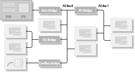
Figure 12-1. Layout of a typical PCI system
圖 12-1. 典型 PCI 系統的布局
The 16-bit hardware addresses associated with PCI peripherals, although mostly hidden in the struct pci_dev object, are still visible occasionally, especially when lists of devices are being used. One such situation is the output of lspci (part of the pciutils package, available with most distributions) and the layout of information in /proc/pci and /proc/bus/pci. The sysfs representation of PCI devices also shows this addressing scheme, with the addition of the PCI domain information.[1] When the hardware address is displayed, it can be shown as two values (an 8-bit bus number and an 8-bit device and function number), as three values (bus, device, and function), or as four values (domain, bus, device, and function); all the values are usually displayed in hexadecimal.
與 PCI 外設相關的 16 位硬件地址,盡管大多隱藏在 struct pci_dev 對象中,但偶爾仍然可見,尤其是在使用設備列表時。這種情況之一是 lspci(pciutils 包的一部分,大多數發行版中都有)的輸出,以及 /proc/pci 和 /proc/bus/pci 中的信息布局。PCI 設備的 sysfs 表示也顯示了這種尋址方案,并增加了 PCI 域信息。[1] 當顯示硬件地址時,它可以顯示為兩個值(8 位總線號和 8 位設備及功能號),三個值(總線、設備和功能),或四個值(域、總線、設備和功能);所有值通常以十六進制顯示。
For example, /proc/bus/pci/devices uses a single 16-bit field (to ease parsing and sorting), while /proc/bus/ busnumber splits the address into three fields. The following shows how those addresses appear, showing only the beginning of the output lines:
例如,/proc/bus/pci/devices 使用一個 16 位字段(便于解析和排序),而 /proc/bus/ busnumber 將地址分為三個字段。以下顯示了這些地址的外觀,僅顯示輸出行的開頭部分:
$ lspci | cut -d: -f1-3
0000:00:00.0 Host bridge
0000:00:00.1 RAM memory
0000:00:00.2 RAM memory
0000:00:02.0 USB Controller
0000:00:04.0 Multimedia audio controller
0000:00:06.0 Bridge
0000:00:07.0 ISA bridge
0000:00:09.0 USB Controller
0000:00:09.1 USB Controller
0000:00:09.2 USB Controller
0000:00:0c.0 CardBus bridge
0000:00:0f.0 IDE interface
0000:00:10.0 Ethernet controller
0000:00:12.0 Network controller
0000:00:13.0 FireWire (IEEE 1394)
0000:00:14.0 VGA compatible controller
$ cat /proc/bus/pci/devices | cut -f1
0000
0001
0002
0010
0020
0030
0038
0048
0049
004a
0060
0078
0080
0090
0098
00a0
$ tree /sys/bus/pci/devices/
/sys/bus/pci/devices/
|-- 0000:00:00.0 -> ../../../devices/pci0000:00/0000:00:00.0
|-- 0000:00:00.1 -> ../../../devices/pci0000:00/0000:00:00.1
|-- 0000:00:00.2 -> ../../../devices/pci0000:00/0000:00:00.2
|-- 0000:00:02.0 -> ../../../devices/pci0000:00/0000:00:02.0
|-- 0000:00:04.0 -> ../../../devices/pci0000:00/0000:00:04.0
|-- 0000:00:06.0 -> ../../../devices/pci0000:00/0000:00:06.0
|-- 0000:00:07.0 -> ../../../devices/pci0000:00/0000:00:07.0
|-- 0000:00:09.0 -> ../../../devices/pci0000:00/0000:00:09.0
|-- 0000:00:09.1 -> ../../../devices/pci0000:00/0000:00:09.1
|-- 0000:00:09.2 -> ../../../devices/pci0000:00/0000:00:09.2
|-- 0000:00:0c.0 -> ../../../devices/pci0000:00/0000:00:0c.0
|-- 0000:00:0f.0 -> ../../../devices/pci0000:00/0000:00:0f.0
|-- 0000:00:10.0 -> ../../../devices/pci0000:00/0000:00:10.0
|-- 0000:00:12.0 -> ../../../devices/pci0000:00/0000:00:12.0
|-- 0000:00:13.0 -> ../../../devices/pci0000:00/0000:00:13.0
`-- 0000:00:14.0 -> ../../../devices/pci0000:00/0000:00:14.0
All three lists of devices are sorted in the same order, since lspci uses the /proc files as its source of information. Taking the VGA video controller as an example, 0x00a0 means 0000:00:14.0 when split into domain (16 bits), bus (8 bits), device (5 bits) and function (3 bits).
所有三個設備列表的排序順序相同,因為 lspci 使用 /proc 文件作為信息來源。以 VGA 視頻控制器為例,0x00a0 表示 0000:00:14.0,拆分為域(16 位)、總線(8 位)、設備(5 位)和功能(3 位)。
The hardware circuitry of each peripheral board answers queries pertaining to three address spaces: memory locations, I/O ports, and configuration registers. The first two address spaces are shared by all the devices on the same PCI bus (i.e., when you access a memory location, all the devices on that PCI bus see the bus cycle at the same time). The configuration space, on the other hand, exploits geographical addressing. Configuration queries address only one slot at a time, so they never collide.
每個外設板的硬件電路會響應有關三個地址空間的查詢:內存位置、I/O 端口和配置寄存器。前兩個地址空間由同一 PCI 總線上的所有設備共享(即,當你訪問一個內存位置時,該 PCI 總線上的所有設備同時看到總線周期)。另一方面,配置空間利用了 地理尋址。配置查詢一次只針對一個插槽,因此它們永遠不會沖突。
As far as the driver is concerned, memory and I/O regions are accessed in the usual ways via inb, readb, and so forth. Configuration transactions, on the other hand, are performed by calling specific kernel functions to access configuration registers. With regard to interrupts, every PCI slot has four interrupt pins, and each device function can use one of them without being concerned about how those pins are routed to the CPU. Such routing is the responsibility of the computer platform and is implemented outside of the PCI bus. Since the PCI specification requires interrupt lines to be shareable, even a processor with a limited number of IRQ lines, such as the x86, can host many PCI interface boards (each with four interrupt pins).
就驅動程序而言,內存和 I/O 區域通過 inb、readb 等方式正常訪問。另一方面,配置事務是通過調用特定的內核函數來訪問配置寄存器來完成的。關于中斷,每個 PCI 插槽都有四個中斷引腳,每個設備功能都可以使用其中的一個,而不必擔心這些引腳如何連接到 CPU。這種路由是計算機平臺的責任,并且是在 PCI 總線之外實現的。由于 PCI 規范要求中斷線是可以共享的,即使是像 x86 這樣具有有限數量 IRQ 線的處理器,也可以托管許多 PCI 接口板(每個板有四個中斷引腳)。
The I/O space in a PCI bus uses a 32-bit address bus (leading to 4 GB of I/O ports), while the memory space can be accessed with either 32-bit or 64-bit addresses. 64-bit addresses are available on more recent platforms. Addresses are supposed to be unique to one device, but software may erroneously configure two devices to the same address, making it impossible to access either one. But this problem never occurs unless a driver is willingly playing with registers it shouldn’t touch. The good news is that every memory and I/O address region offered by the interface board can be remapped by means of configuration transactions. That is, the firmware initializes PCI hardware at system boot, mapping each region to a different address to avoid collisions.[2] The addresses to which these regions are currently mapped can be read from the configuration space, so the Linux driver can access its devices without probing. After reading the configuration registers, the driver can safely access its hardware.
PCI 總線中的 I/O 空間使用 32 位地址總線(導致有 4 GB 的 I/O 端口),而內存空間可以用 32 位或 64 位地址訪問。較新的平臺上可以使用 64 位地址。地址應該是唯一的,但軟件可能會錯誤地將兩個設備配置為相同的地址,使得無法訪問任何一個。但除非驅動程序故意去操作它不應該觸碰的寄存器,否則這個問題永遠不會出現。好消息是,接口板提供的每個內存和 I/O 地址區域都可以通過配置事務重新映射。也就是說,固件在系統啟動時初始化 PCI 硬件,將每個區域映射到不同的地址以避免沖突。[2] 這些區域當前映射到的地址可以從配置空間讀取,因此 Linux 驅動程序可以無需探測地訪問其設備。在讀取配置寄存器之后,驅動程序可以安全地訪問其硬件。
The PCI configuration space consists of 256 bytes for each device function (except for PCI Express devices, which have 4 KB of configuration space for each function), and the layout of the configuration registers is standardized. Four bytes of the configuration space hold a unique function ID, so the driver can identify its device by looking for the specific ID for that peripheral.[3] In summary, each device board is geographically addressed to retrieve its configuration registers; the information in those registers can then be used to perform normal I/O access, without the need for further geographic addressing.
PCI 配置空間由每個設備功能的 256 字節組成(PCI Express 設備除外,每個功能有 4 KB 的配置空間),配置寄存器的布局是標準化的。配置空間的四個字節包含一個唯一的功能 ID,因此驅動程序可以通過查找該外設的特定 ID 來識別其設備。[3] 總之,每個設備板通過地理尋址來檢索其配置寄存器;然后可以使用這些寄存器中的信息來執行正常的 I/O 訪問,而無需進一步的地理尋址。
It should be clear from this description that the main innovation of the PCI interface standard over ISA is the configuration address space. Therefore, in addition to the usual driver code, a PCI driver needs the ability to access the configuration space, in order to save itself from risky probing tasks.
從這個描述中應該清楚地看出,PCI 接口標準相對于 ISA 的主要創新是配置地址空間。因此,除了通常的驅動程序代碼外,PCI 驅動程序還需要能夠訪問配置空間,以避免冒險的探測任務。
For the remainder of this chapter, we use the word device to refer to a device function, because each function in a multifunction board acts as an independent entity. When we refer to a device, we mean the tuple “domain number, bus number, device number, and function number.”
在本章的其余部分中,我們用 device(設備)一詞來指代設備功能,因為多功能板上的每個功能都作為一個獨立實體來運行。當我們提到一個設備時,我們指的是“域號、總線號、設備號和功能號”這一組信息。
Boot Time
啟動時間
To see how PCI works, we start from system boot, since that’s when the devices are configured.
要了解 PCI 的工作方式,我們需要從系統啟動開始,因為這是設備被配置的時候。
When power is applied to a PCI device, the hardware remains inactive. In other words, the device responds only to configuration transactions. At power on, the device has no memory and no I/O ports mapped in the computer’s address space; every other device-specific feature, such as interrupt reporting, is disabled as well.
當電源被應用到 PCI 設備時,硬件保持非活動狀態。換句話說,設備只響應配置事務。在加電時,設備沒有內存和 I/O 端口被映射到計算機的地址空間中;所有其他設備特定的功能(如中斷報告)也都被禁用。
Fortunately, every PCI motherboard is equipped with PCI-aware firmware, called the BIOS, NVRAM, or PROM, depending on the platform. The firmware offers access to the device configuration address space by reading and writing registers in the PCI controller.
幸運的是,每塊 PCI 主板都配備了支持 PCI 的固件,根據平臺的不同,這些固件被稱為 BIOS、NVRAM 或 PROM。固件通過讀取和寫入 PCI 控制器中的寄存器來提供對設備配置地址空間的訪問。
At system boot, the firmware (or the Linux kernel, if so configured) performs configuration transactions with every PCI peripheral in order to allocate a safe place for each address region it offers. By the time a device driver accesses the device, its memory and I/O regions have already been mapped into the processor’s address space. The driver can change this default assignment, but it never needs to do that.
在系統啟動時,固件(或者如果配置了的話,Linux 內核)會與每個 PCI 外設執行配置事務,以便為每個地址區域分配一個安全的位置。當設備驅動程序訪問設備時,其內存和 I/O 區域已經被映射到處理器的地址空間中。驅動程序可以更改這個默認分配,但它永遠不需要這么做。
As suggested, the user can look at the PCI device list and the devices’ configuration registers by reading /proc/bus/pci/devices and */proc/bus/pci/*/*. The former is a text file with (hexadecimal) device information, and the latter are binary files that report a snapshot of the configuration registers of each device, one file per device. The individual PCI device directories in the sysfs tree can be found in /sys/bus/pci/devices. A PCI device directory contains a number of different files:
如建議的那樣,用戶可以通過閱讀 /proc/bus/pci/devices 和 /proc/bus/pci/*/ 來查看 PCI 設備列表和設備的配置寄存器。前者是一個包含(十六進制)設備信息的文本文件,后者是二進制文件,報告每個設備的配置寄存器的快照,每個設備一個文件。sysfs 樹中的各個 PCI 設備目錄可以在 /sys/bus/pci/devices 中找到。PCI 設備目錄包含許多不同的文件:
$ tree /sys/bus/pci/devices/0000:00:10.0
/sys/bus/pci/devices/0000:00:10.0
|-- class
|-- config
|-- detach_state
|-- device
|-- irq
|-- power
| `-- state
|-- resource
|-- subsystem_device
|-- subsystem_vendor
`-- vendor
The file config is a binary file that allows the raw PCI config information to be read from the device (just like the /proc/bus/pci/*/* provides.) The files vendor, device, subsystem_device, subsystem_vendor, and class all refer to the specific values of this PCI device (all PCI devices provide this information.) The file irq shows the current IRQ assigned to this PCI device, and the file resource shows the current memory resources allocated by this device.
文件 config 是一個二進制文件,允許從設備中讀取原始的 PCI 配置信息(就像 /proc/bus/pci/*/* 提供的一樣)。文件 vendor、device、subsystem_device、subsystem_vendor 和 class 都指的是這個 PCI 設備的特定值(所有 PCI 設備都提供這些信息)。文件 irq 顯示分配給此 PCI 設備的當前 IRQ,文件 resource 顯示此設備分配的當前內存資源。
Configuration Registers and Initialization
配置寄存器和初始化
In this section, we look at the configuration registers that PCI devices contain. All PCI devices feature at least a 256-byte address space. The first 64 bytes are standardized, while the rest are device dependent. Figure 12-2 shows the layout of the device-independent configuration space.
在本節中,我們查看 PCI 設備包含的配置寄存器。所有 PCI 設備至少具有 256 字節的地址空間。前 64 字節是標準化的,其余部分則取決于設備。Figure 12-2 顯示了設備獨立配置空間的布局。
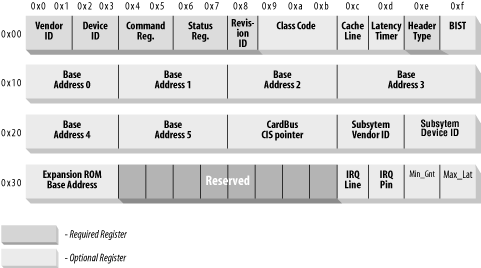
Figure 12-2. The standardized PCI configuration registers
圖 12-2. 標準化的 PCI 配置寄存器
As the figure shows, some of the PCI configuration registers are required and some are optional. Every PCI device must contain meaningful values in the required registers, whereas the contents of the optional registers depend on the actual capabilities of the peripheral. The optional fields are not used unless the contents of the required fields indicate that they are valid. Thus, the required fields assert the board’s capabilities, including whether the other fields are usable.
如圖所示,某些 PCI 配置寄存器是必需的,而某些是可選的。每個 PCI 設備都必須在其必需的寄存器中包含有意義的值,而可選寄存器的內容則取決于外設的實際功能。除非必需字段的內容表明它們是有效的,否則不會使用可選字段。因此,必需字段聲明了板卡的功能,包括其他字段是否可用。
It’s interesting to note that the PCI registers are always little-endian. Although the standard is designed to be architecture independent, the PCI designers sometimes show a slight bias toward the PC environment. The driver writer should be careful about byte ordering when accessing multibyte configuration registers; code that works on the PC might not work on other platforms. The Linux developers have taken care of the byte-ordering problem (see the next section, Section 12.1.8), but the issue must be kept in mind. If you ever need to convert data from host order to PCI order or vice versa, you can resort to the functions defined in <asm/byteorder.h>, introduced in Chapter 11, knowing that PCI byte order is little-endian.
值得注意的是,PCI 寄存器始終是小端模式。盡管該標準旨在與架構無關,但 PCI 設計者有時會略微偏向于 PC 環境。驅動程序編寫者在訪問多字節配置寄存器時應注意字節順序;在 PC 上工作的代碼可能無法在其他平臺上工作。Linux 開發者已經解決了字節順序問題(參見下一節 Section 12.1.8),但必須牢記這一問題。如果需要將數據從主機順序轉換為 PCI 順序,或者反之,可以使用在 Chapter 11 中介紹的 <asm/byteorder.h> 中定義的函數,要知道 PCI 字節順序是小端模式。
Describing all the configuration items is beyond the scope of this book. Usually, the technical documentation released with each device describes the supported registers. What we’re interested in is how a driver can look for its device and how it can access the device’s configuration space.
描述所有配置項超出了本書的范圍。通常,隨每個設備發布的技術文檔會描述支持的寄存器。我們感興趣的是驅動程序如何查找其設備以及如何訪問設備的配置空間。
Three or five PCI registers identify a device: vendorID, deviceID, and class are the three that are always used. Every PCI manufacturer assigns proper values to these read-only registers, and the driver can use them to look for the device. Additionally, the fields subsystem vendorID and subsystem deviceID are sometimes set by the vendor to further differentiate similar devices.
三個或五個 PCI 寄存器用于識別設備:vendorID、deviceID 和 class 是始終使用的三個寄存器。每個 PCI 制造商都為這些只讀寄存器分配適當的值,驅動程序可以使用它們來查找設備。此外,subsystem vendorID 和 subsystem deviceID 字段有時由供應商設置,以進一步區分類似的設備。
Let’s look at these registers in more detail:
讓我們更詳細地看看這些寄存器:
-
vendorID- This 16-bit register identifies a hardware manufacturer. For instance, every Intel device is marked with the same vendor number,
0x8086. There is a global registry of such numbers, maintained by the PCI Special Interest Group, and manufacturers must apply to have a unique number assigned to them. - 這個 16 位寄存器用于識別硬件制造商。例如,所有英特爾設備都標有相同的供應商編號
0x8086。有一個全球性的此類編號注冊表,由 PCI 特殊興趣小組維護,制造商必須申請分配一個唯一的編號。
- This 16-bit register identifies a hardware manufacturer. For instance, every Intel device is marked with the same vendor number,
-
deviceID- This is another 16-bit register, selected by the manufacturer; no official registration is required for the device ID. This ID is usually paired with the vendor ID to make a unique 32-bit identifier for a hardware device. We use the word signature to refer to the vendor and device ID pair. A device driver usually relies on the signature to identify its device; you can find what value to look for in the hardware manual for the target device.
- 這是另一個 16 位寄存器,由制造商選擇;設備 ID 不需要官方注冊。此 ID 通常與供應商 ID 配對,形成一個硬件設備的唯一 32 位標識符。我們用“簽名”一詞來指代供應商 ID 和設備 ID 的組合。設備驅動程序通常依賴簽名來識別其設備;您可以在目標設備的硬件手冊中找到要查找的值。
-
class- Every peripheral device belongs to a class. The
classregister is a 16-bit value whose top 8 bits identify the “base class” (or group). For example, “ethernet” and “token ring” are two classes belonging to the “network” group, while the “serial” and “parallel” classes belong to the “communication” group. Some drivers can support several similar devices, each of them featuring a different signature but all belonging to the same class; these drivers can rely on theclassregister to identify their peripherals, as shown later. - 每個外設都屬于一個“類別”。
class寄存器是一個 16 位的值,其最高 8 位標識“基礎類別”(或“組”)。例如,“以太網”和“令牌環”是屬于“網絡”組的兩個類別,而“串行”和“并行”類別屬于“通信”組。有些驅動程序可以支持幾種類似的設備,每種設備都有不同的簽名,但都屬于同一個類別;這些驅動程序可以依賴class寄存器來識別其外設,稍后會展示。
- Every peripheral device belongs to a class. The
-
subsystem vendorIDsubsystem deviceID- These fields can be used for further identification of a device. If the chip is a generic interface chip to a local (onboard) bus, it is often used in several completely different roles, and the driver must identify the actual device it is talking with. The subsystem identifiers are used to this end.
- 這些字段可用于進一步識別設備。如果芯片是用于本地(板載)總線的通用接口芯片,它通常用于幾種完全不同的角色,驅動程序必須識別它正在通信的實際設備。子系統標識符用于此目的。
Using these different identifiers, a PCI driver can tell the kernel what kind of devices it supports. The struct pci_device_id structure is used to define a list of the different types of PCI devices that a driver supports. This structure contains the following fields:
通過使用這些不同的標識符,PCI 驅動程序可以告訴內核它支持哪些類型的設備。struct pci_device_id 結構用于定義驅動程序支持的不同類型的 PCI 設備列表。這個結構包含以下字段:
-
_ _u32 vendor;_ _u32 device;- These specify the PCI vendor and device IDs of a device. If a driver can handle any vendor or device ID, the value
PCI_ANY_IDshould be used for these fields. - 這些字段指定設備的 PCI 供應商 ID 和設備 ID。如果驅動程序可以處理任何供應商或設備 ID,則應為這些字段使用
PCI_ANY_ID值。
- These specify the PCI vendor and device IDs of a device. If a driver can handle any vendor or device ID, the value
-
_ _u32 subvendor;_ _u32 subdevice;- These specify the PCI subsystem vendor and subsystem device IDs of a device. If a driver can handle any type of subsystem ID, the value
PCI_ANY_IDshould be used for these fields. - 這些字段指定設備的 PCI 子系統供應商和子系統設備 ID。如果驅動程序可以處理任何類型的子系統 ID,則應為這些字段使用
PCI_ANY_ID值。
- These specify the PCI subsystem vendor and subsystem device IDs of a device. If a driver can handle any type of subsystem ID, the value
-
_ _u32 class;_ _u32 class_mask;- These two values allow the driver to specify that it supports a type of PCI class device. The different classes of PCI devices (a VGA controller is one example) are described in the PCI specification. If a driver can handle any type of subsystem ID, the value
PCI_ANY_IDshould be used for these fields. - 這兩個值允許驅動程序指定它支持一種 PCI 類別設備。PCI 規范中描述了不同類別的 PCI 設備(VGA 控制器就是一個例子)。如果驅動程序可以處理任何類型的子系統 ID,則應為這些字段使用
PCI_ANY_ID值。
- These two values allow the driver to specify that it supports a type of PCI class device. The different classes of PCI devices (a VGA controller is one example) are described in the PCI specification. If a driver can handle any type of subsystem ID, the value
-
kernel_ulong_t driver_data;- This value is not used to match a device but is used to hold information that the PCI driver can use to differentiate between different devices if it wants to.
- 此值不用于匹配設備,而是用于保存 PCI 驅動程序可以用來區分不同設備的信息(如果它想的話)。
There are two helper macros that should be used to initialize a struct pci_device_id structure:
有兩個輔助宏可用于初始化 struct pci_device_id 結構:
-
PCI_DEVICE(vendor, device)- This creates a
structpci_device_idthat matches only the specific vendor and device ID. The macro sets thesubvendorandsubdevicefields of the structure toPCI_ANY_ID. - 此宏創建一個
structpci_device_id,僅匹配特定的供應商和設備 ID。該宏將結構的subvendor和subdevice字段設置為PCI_ANY_ID。
- This creates a
-
PCI_DEVICE_CLASS(device_class, device_class_mask)- This creates a
structpci_device_idthat matches a specific PCI class. - 此宏創建一個
structpci_device_id,匹配特定的 PCI 類別。
- This creates a
An example of using these macros to define the type of devices a driver supports can be found in the following kernel files:
以下內核文件中可以找到使用這些宏定義驅動程序支持的設備類型的示例:
drivers/usb/host/ehci-hcd.c:static const struct pci_device_id pci_ids[ ] = { {/* handle any USB 2.0 EHCI controller */PCI_DEVICE_CLASS(((PCI_CLASS_SERIAL_USB << 8) | 0x20), ~0),.driver_data = (unsigned long) &ehci_driver,},{ /* end: all zeroes */ }
};drivers/i2c/busses/i2c-i810.c:static struct pci_device_id i810_ids[ ] = {{ PCI_DEVICE(PCI_VENDOR_ID_INTEL, PCI_DEVICE_ID_INTEL_82810_IG1) },{ PCI_DEVICE(PCI_VENDOR_ID_INTEL, PCI_DEVICE_ID_INTEL_82810_IG3) },{ PCI_DEVICE(PCI_VENDOR_ID_INTEL, PCI_DEVICE_ID_INTEL_82810E_IG) },{ PCI_DEVICE(PCI_VENDOR_ID_INTEL, PCI_DEVICE_ID_INTEL_82815_CGC) },{ PCI_DEVICE(PCI_VENDOR_ID_INTEL, PCI_DEVICE_ID_INTEL_82845G_IG) },{ 0, },
};
These examples create a list of struct pci_device_id structures, with an empty structure set to all zeros as the last value in the list. This array of IDs is used in the struct pci_driver (described below), and it is also used to tell user space which devices this specific driver supports.
這些示例創建了一個 struct pci_device_id 結構列表,列表的最后一個值是一個設置為全零的空結構。這個 ID 數組用于 struct pci_driver(稍后描述),也用于告訴用戶空間這個特定驅動程序支持哪些設備。
MODULE_DEVICE_TABLE
模塊設備表
This pci_device_id structure needs to be exported to user space to allow the hotplug and module loading systems to know what module works with what hardware devices. The macro MODULE_DEVICE_TABLE accomplishes this. An example is:
需要將此 pci_device_id 結構導出到用戶空間,以便讓熱插拔和模塊加載系統知道哪個模塊與哪個硬件設備配合工作。MODULE_DEVICE_TABLE 宏可以實現這一點。示例如下:
MODULE_DEVICE_TABLE(pci, i810_ids);
This statement creates a local variable called _ _mod_pci_device_table that points to the list of struct pci_device_id. Later in the kernel build process, the depmod program searches all modules for the symbol _ _mod_pci_device_table. If that symbol is found, it pulls the data out of the module and adds it to the file /lib/modules/KERNEL_VERSION/modules.pcimap. After depmod completes, all PCI devices that are supported by modules in the kernel are listed, along with their module names, in that file. When the kernel tells the hotplug system that a new PCI device has been found, the hotplug system uses the modules.pcimap file to find the proper driver to load.
該語句創建了一個名為 _ _mod_pci_device_table 的局部變量,指向 struct pci_device_id 列表。在內核構建過程的后續階段中,depmod 程序會在所有模塊中搜索 _ _mod_pci_device_table 符號。如果找到該符號,它會將模塊中的數據提取出來,并將其添加到文件 /lib/modules/KERNEL_VERSION/modules.pcimap 中。depmod 完成后,內核中模塊支持的所有 PCI 設備都會被列在該文件中,并附上它們的模塊名稱。當內核告知熱插拔系統發現了一個新的 PCI 設備時,熱插拔系統會使用 modules.pcimap 文件來找到要加載的正確驅動程序。
Registering a PCI Driver
注冊 PCI 驅動程序
The main structure that all PCI drivers must create in order to be registered with the kernel properly is the struct pci_driver structure. This structure consists of a number of function callbacks and variables that describe the PCI driver to the PCI core. Here are the fields in this structure that a PCI driver needs to be aware of:
所有 PCI 驅動程序必須創建的主要結構是 struct pci_driver 結構,以便正確地在內核中注冊。該結構包含許多函數回調和變量,用于向 PCI 核心描述 PCI 驅動程序。以下是 PCI 驅動程序需要了解的該結構中的字段:
-
const char *name;- The name of the driver. It must be unique among all PCI drivers in the kernel and is normally set to the same name as the module name of the driver. It shows up in sysfs under /sys/bus/pci/drivers/ when the driver is in the kernel.
- 驅動程序的名稱。它必須在內核中的所有 PCI 驅動程序中是唯一的,并且通常設置為與驅動程序模塊名稱相同的名稱。當驅動程序在內核中時,它會出現在 sysfs 的 /sys/bus/pci/drivers/ 下。
-
const struct pci_device_id *id_table;- Pointer to the
structpci_device_idtable described earlier in this chapter. - 指向本章前面描述的
structpci_device_id表的指針。
- Pointer to the
-
int (*probe) (struct pci_dev *dev, const struct pci_device_id *id);- Pointer to the probe function in the PCI driver. This function is called by the PCI core when it has a
struct pci_devthat it thinks this driver wants to control. A pointer to thestructpci_device_idthat the PCI core used to make this decision is also passed to this function. If the PCI driver claims thestructpci_devthat is passed to it, it should initialize the device properly and return0. If the driver does not want to claim the device, or an error occurs, it should return a negative error value. More details about this function follow later in this chapter. - 指向 PCI 驅動程序中的探測函數的指針。當 PCI 核心有一個
struct pci_dev,它認為這個驅動程序想要控制時,會調用這個函數。PCI 核心用來做出這個決定的structpci_device_id的指針也會傳遞給這個函數。如果 PCI 驅動程序聲稱傳遞給它的structpci_dev,它應該正確初始化設備并返回0。如果驅動程序不想聲稱該設備,或者發生錯誤,它應該返回一個負的錯誤值。關于這個函數的更多細節將在本章后面介紹。
- Pointer to the probe function in the PCI driver. This function is called by the PCI core when it has a
-
void (*remove) (struct pci_dev *dev);- Pointer to the function that the PCI core calls when the
structpci_devis being removed from the system, or when the PCI driver is being unloaded from the kernel. More details about this function follow later in this chapter. - 指向 PCI 核心在從系統中移除
structpci_dev,或者從內核中卸載 PCI 驅動程序時調用的函數的指針。關于這個函數的更多細節將在本章后面介紹。
- Pointer to the function that the PCI core calls when the
-
int (*suspend) (struct pci_dev *dev, u32 state);- Pointer to the function that the PCI core calls when the
structpci_devis being suspended. The suspend state is passed in thestatevariable. This function is optional; a driver does not have to provide it. - 指向 PCI 核心在掛起
structpci_dev時調用的函數的指針。掛起狀態通過state變量傳遞。這個函數是可選的;驅動程序不需要提供它。
- Pointer to the function that the PCI core calls when the
-
int (*resume) (struct pci_dev *dev);- Pointer to the function that the PCI core calls when the
structpci_devis being resumed. It is always called aftersuspendhas been called. This function is optional; a driver does not have to provide it. - 指向 PCI 核心在恢復
structpci_dev時調用的函數的指針。它總是在調用suspend之后被調用。這個函數是可選的;驅動程序不需要提供它。
- Pointer to the function that the PCI core calls when the
In summary, to create a proper struct pci_driver structure, only four fields need to be initialized:
總之,要創建一個合適的 struct pci_driver 結構,只需要初始化四個字段:
static struct pci_driver pci_driver = {.name = "pci_skel",.id_table = ids,.probe = probe,.remove = remove,
};
To register the struct pci_driver with the PCI core, a call to pci_register_driver is made with a pointer to the struct pci_driver. This is traditionally done in the module initialization code for the PCI driver:
要將 struct pci_driver 注冊到 PCI 核心,需要使用指向 struct pci_driver 的指針調用 pci_register_driver。這通常在 PCI 驅動程序的模塊初始化代碼中完成:
static int _ _init pci_skel_init(void)
{return pci_register_driver(&pci_driver);
}
Note that the pci_register_driver function either returns a negative error number or 0 if everything was registered successfully. It does not return the number of devices that were bound to the driver or an error number if no devices were bound to the driver. This is a change from kernels prior to the 2.6 release and was done because of the following situations:
請注意,pci_register_driver 函數如果注冊成功會返回 0,否則返回一個負的錯誤編號。它不會返回綁定到驅動程序的設備數量,或者如果沒有設備綁定到驅動程序,則返回一個錯誤編號。這與 2.6 版本之前的內核有所不同,原因是以下情況:
-
On systems that support PCI hotplug, or CardBus systems, a PCI device can appear or disappear at any point in time. It is helpful if drivers can be loaded before the device appears, to reduce the time it takes to initialize a device.
- 在支持 PCI 熱插拔或 CardBus 的系統中,PCI 設備可以在任何時候出現或消失。如果驅動程序可以在設備出現之前加載,將有助于減少初始化設備所需的時間。
-
The 2.6 kernel allows new PCI IDs to be dynamically allocated to a driver after it has been loaded. This is done through the file
new_idthat is created in all PCI driver directories in sysfs. This is very useful if a new device is being used that the kernel doesn’t know about just yet. A user can write the PCI ID values to the new_id file, and then the driver binds to the new device. If a driver was not allowed to load until a device was present in the system, this interface would not be able to work.- 2.6 內核允許在驅動程序加載后動態分配新的 PCI ID。這是通過在 sysfs 中所有 PCI 驅動程序目錄中創建的文件
new_id來完成的。如果正在使用內核尚未知曉的新設備,這將非常有用。用戶可以將 PCI ID 值寫入 new_id 文件,然后驅動程序將綁定到新設備。如果驅動程序在系統中存在設備之前不允許加載,這個接口將無法工作。
- 2.6 內核允許在驅動程序加載后動態分配新的 PCI ID。這是通過在 sysfs 中所有 PCI 驅動程序目錄中創建的文件
When the PCI driver is to be unloaded, the struct pci_driver needs to be unregistered from the kernel. This is done with a call to pci_unregister_driver. When this call happens, any PCI devices that were currently bound to this driver are removed, and the remove function for this PCI driver is called before the pci_unregister_driver function returns.
當要卸載 PCI 驅動程序時,需要從內核中注銷 struct pci_driver。這是通過調用 pci_unregister_driver 來完成的。當進行此調用時,當前綁定到此驅動程序的所有 PCI 設備都將被移除,并且在 pci_unregister_driver 函數返回之前,將調用此 PCI 驅動程序的 remove 函數。
static void _ _exit pci_skel_exit(void)
{pci_unregister_driver(&pci_driver);
}
Old-Style PCI Probing
舊式 PCI 探測
In older kernel versions, the function, pci_register_driver, was not always used by PCI drivers. Instead, they would either walk the list of PCI devices in the system by hand, or they would call a function that could search for a specific PCI device. The ability to walk the list of PCI devices in the system within a driver has been removed from the 2.6 kernel in order to prevent drivers from crashing the kernel if they happened to modify the PCI device lists while a device was being removed at the same time.
在舊版本的內核中,PCI 驅動程序并不總是使用 pci_register_driver 函數。相反,它們會手動遍歷系統中的 PCI 設備列表,或者調用一個可以搜索特定 PCI 設備的函數。在 2.6 內核中,已經移除了驅動程序在系統中遍歷 PCI 設備列表的能力,以防止驅動程序在設備被移除的同時修改 PCI 設備列表而導致內核崩潰。
If the ability to find a specific PCI device is really needed, the following functions are available:
如果確實需要找到一個特定的 PCI 設備,以下函數是可用的:
struct pci_dev *pci_get_device(unsigned int vendor, unsigned int device,struct pci_dev *from);- This function scans the list of PCI devices currently present in the system, and if the input arguments match the specified
vendoranddeviceIDs, it increments the reference count on thestructpci_devvariable found, and returns it to the caller. This prevents the structure from disappearing without any notice and ensures that the kernel does not oops. After the driver is done with thestructpci_devreturned by the function, it must call the function pci_dev_put to decrement the usage count properly back to allow the kernel to clean up the device if it is removed. - 此函數掃描系統中當前存在的 PCI 設備列表,如果輸入參數與指定的
vendor和deviceID 匹配,則會增加找到的structpci_dev變量的引用計數,并將其返回給調用者。這可以防止該結構在沒有任何通知的情況下消失,并確保內核不會出現錯誤。驅動程序在使用完函數返回的structpci_dev后,必須調用 pci_dev_put 函數來正確減少使用計數,以便內核在設備被移除時清理設備。
- This function scans the list of PCI devices currently present in the system, and if the input arguments match the specified
The from argument is used to get hold of multiple devices with the same signature; the argument should point to the last device that has been found, so that the search can continue instead of restarting from the head of the list. To find the first device, from is specified as NULL. If no (further) device is found, NULL is returned.
from 參數用于獲取具有相同簽名的多個設備;該參數應指向已找到的最后一個設備,以便繼續搜索而不是從列表頭部重新開始。要查找第一個設備,from 應指定為 NULL。如果沒有(進一步)找到設備,則返回 NULL。
An example of how to use this function properly is:
正確使用此函數的示例如下:
struct pci_dev *dev;
dev = pci_get_device(PCI_VENDOR_FOO, PCI_DEVICE_FOO, NULL);
if (dev) {/* Use the PCI device */...pci_dev_put(dev);
}
This function cannot be called from interrupt context. If it is, a warning is printed out to the system log.
此函數不能從中斷上下文中調用。如果這樣做了,系統日志中會打印出警告信息。
struct pci_dev *pci_get_subsys(unsigned int vendor, unsigned int device,unsigned int ss_vendor, unsigned int ss_device, struct pci_dev *from);- This function works just like pci_get_device, but it allows the subsystem vendor and subsystem device IDs to be specified when looking for the device.
- 此函數的工作方式與 pci_get_device 完全相同,但在查找設備時,它允許指定子系統供應商和子系統設備 ID。
This function cannot be called from interrupt context. If it is, a warning is printed out to the system log.
此函數不能從中斷上下文中調用。如果這樣做了,系統日志中會打印出警告信息。
struct pci_dev *pci_get_slot(struct pci_bus *bus, unsigned int devfn);- This function searches the list of PCI devices in the system on the specified
struct pci_busfor the specified device and function number of the PCI device. If a device is found that matches, its reference count is incremented and a pointer to it is returned. When the caller is finished accessing thestructpci_dev, it must call pci_dev_put. - 此函數在系統中指定的
struct pci_bus上的 PCI 設備列表中搜索指定的設備和功能號的 PCI 設備。如果找到匹配的設備,其引用計數將增加,并返回指向它的指針。調用者在訪問完structpci_dev后,必須調用 pci_dev_put。
- This function searches the list of PCI devices in the system on the specified
All of these functions cannot be called from interrupt context. If they are, a warning is printed out to the system log.
所有這些函數都不能從中斷上下文中調用。如果這樣做了,系統日志中會打印出警告信息。
Enabling the PCI Device
啟用 PCI 設備
In the probe function for the PCI driver, before the driver can access any device resource (I/O region or interrupt) of the PCI device, the driver must call the pci_enable_device function:
在 PCI 驅動程序的 probe 函數中,在驅動程序可以訪問 PCI 設備的任何設備資源(I/O 區域或中斷)之前,驅動程序必須調用 pci_enable_device 函數:
int pci_enable_device(struct pci_dev *dev);- This function actually enables the device. It wakes up the device and in some cases also assigns its interrupt line and I/O regions. This happens, for example, with CardBus devices (which have been made completely equivalent to PCI at the driver level).
- 此函數實際上啟用了設備。它喚醒設備,在某些情況下還會為其分配中斷線和 I/O 區域。例如,CardBus 設備(在驅動程序級別已完全等同于 PCI)就是這種情況。
Accessing the Configuration Space
訪問配置空間
After the driver has detected the device, it usually needs to read from or write to the three address spaces: memory, port, and configuration. In particular, accessing the configuration space is vital to the driver, because it is the only way it can find out where the device is mapped in memory and in the I/O space.
在驅動程序檢測到設備之后,它通常需要讀取或寫入三個地址空間:內存、端口和配置。特別是,訪問配置空間對驅動程序至關重要,因為這是它唯一可以找到設備在內存和 I/O 空間中映射位置的方法。
Because the microprocessor has no way to access the configuration space directly, the computer vendor has to provide a way to do it. To access configuration space, the CPU must write and read registers in the PCI controller, but the exact implementation is vendor dependent and not relevant to this discussion, because Linux offers a standard interface to access the configuration space.
由于微處理器無法直接訪問配置空間,因此計算機供應商必須提供一種方法來實現。為了訪問配置空間,CPU 必須在 PCI 控制器中寫入和讀取寄存器,但具體實現取決于供應商,與本次討論無關,因為 Linux 提供了一個標準接口來訪問配置空間。
As far as the driver is concerned, the configuration space can be accessed through 8-bit, 16-bit, or 32-bit data transfers. The relevant functions are prototyped in <linux/pci.h>:
就驅動程序而言,配置空間可以通過 8 位、16 位或 32 位數據傳輸來訪問。相關的函數在 <linux/pci.h> 中聲明:
-
int pci_read_config_byte(struct pci_dev *dev, int where, u8 *val);int pci_read_config_word(struct pci_dev *dev, int where, u16 *val);int pci_read_config_dword(struct pci_dev *dev, int where, u32 *val);- Read one, two, or four bytes from the configuration space of the device identified by
dev. Thewhereargument is the byte offset from the beginning of the configuration space. The value fetched from the configuration space is returned through thevalpointer, and the return value of the functions is an error code. The word and dword functions convert the value just read from little-endian to the native byte order of the processor, so you need not deal with byte ordering. - 從由
dev指定的設備的配置空間中讀取一個、兩個或四個字節。where參數是從配置空間開頭的字節偏移量。從配置空間中獲取的值通過val指針返回,函數的返回值是一個錯誤代碼。word 和 dword 函數將剛剛讀取的值從小端模式轉換為處理器的本地字節順序,因此您無需處理字節順序。
- Read one, two, or four bytes from the configuration space of the device identified by
-
int pci_write_config_byte(struct pci_dev *dev, int where, u8 val);int pci_write_config_word(struct pci_dev *dev, int where, u16 val);int pci_write_config_dword(struct pci_dev *dev, int where, u32 val);- Write one, two, or four bytes to the configuration space. The device is identified by
devas usual, and the value being written is passed asval. The word and dword functions convert the value to little-endian before writing to the peripheral device. - 向配置空間寫入一個、兩個或四個字節。設備如往常一樣通過
dev識別,要寫入的值作為val傳遞。word 和 dword 函數在寫入外圍設備之前將值轉換為小端模式。
- Write one, two, or four bytes to the configuration space. The device is identified by
All of the previous functions are implemented as inline functions that really call the following functions. Feel free to use these functions instead of the above in case the driver does not have access to a struct pci_dev at any particular moment in time:
所有前面的函數都作為內聯函數實現,實際上調用了以下函數。如果驅動程序在某個特定時刻沒有訪問 struct pci_dev 的權限,可以自由使用這些函數代替上述函數:
-
int pci_bus_read_config_byte (struct pci_bus *bus, unsigned int devfn, intwhere, u8 *val);int pci_bus_read_config_word (struct pci_bus *bus, unsigned int devfn, intwhere, u16 *val);int pci_bus_read_config_dword (struct pci_bus *bus, unsigned int devfn, intwhere, u32 *val);- Just like the pci_read_ functions, but
structpci_bus*anddevfnvariables are needed instead of astructpci_dev *. - 與 pci_read_ 函數類似,但需要
structpci_bus*和devfn變量,而不是structpci_dev *。
- Just like the pci_read_ functions, but
-
int pci_bus_write_config_byte (struct pci_bus *bus, unsigned int devfn, intwhere, u8 val);int pci_bus_write_config_word (struct pci_bus *bus, unsigned int devfn, intwhere, u16 val);int pci_bus_write_config_dword (struct pci_bus *bus, unsigned int devfn, intwhere, u32 val);- Just like the pci_write_ functions, but
structpci_bus*anddevfnvariables are needed instead of astruct pci_dev *. - 與 pci_write_ 函數類似,但需要
structpci_bus*和devfn變量,而不是struct pci_dev *。
- Just like the pci_write_ functions, but
The best way to address the configuration variables using the pci_read_ functions is by means of the symbolic names defined in <linux/pci.h>. For example, the following small function retrieves the revision ID of a device by passing the symbolic name for where to pci_read_config_byte:
使用 pci_read_ 函數訪問配置變量的最佳方式是通過在 <linux/pci.h> 中定義的符號名稱。例如,以下小函數通過將 where 的符號名稱傳遞給 pci_read_config_byte 來檢索設備的修訂 ID:
static unsigned char skel_get_revision(struct pci_dev *dev)
{u8 revision;pci_read_config_byte(dev, PCI_REVISION_ID, &revision);return revision;
}
Accessing the I/O and Memory Spaces
訪問 I/O 和內存空間
A PCI device implements up to six I/O address regions. Each region consists of either memory or I/O locations. Most devices implement their I/O registers in memory regions, because it’s generally a saner approach. However, unlike normal memory, I/O registers should not be cached by the CPU because each access can have side effects. The PCI device that implements I/O registers as a memory region marks the difference by setting a “memory-is-prefetchable” bit in its configuration register.[4] If the memory region is marked as prefetchable, the CPU can cache its contents and do all sorts of optimization with it; nonprefetchable memory access, on the other hand, can’t be optimized because each access can have side effects, just as with I/O ports. Peripherals that map their control registers to a memory address range declare that range as nonprefetchable, whereas something like video memory on PCI boards is prefetchable. In this section, we use the word region to refer to a generic I/O address space that is memory-mapped or port-mapped.
PCI 設備實現了多達六個 I/O 地址區域。每個區域由內存或 I/O 位置組成。大多數設備在其內存區域中實現 I/O 寄存器,因為這通常是一種更合理的方法。然而,與普通內存不同,I/O 寄存器不應被 CPU 緩存,因為每次訪問都可能產生副作用。實現 I/O 寄存器為內存區域的 PCI 設備通過在其配置寄存器中設置“內存可預取”位來標記差異。[4] 如果內存區域被標記為可預取,CPU 可以緩存其內容并對其進行各種優化;而非預取內存訪問則無法優化,因為每次訪問都可能產生副作用,就像 I/O 端口一樣。將控制寄存器映射到內存地址范圍的外設會聲明該范圍為不可預取,而像 PCI 板上的視頻內存則是可預取的。在本節中,我們使用“區域”一詞來指代一個通用的 I/O 地址空間,它可以是內存映射或端口映射的。
An interface board reports the size and current location of its regions using configuration registers—the six 32-bit registers shown in Figure 12-2, whose symbolic names are PCI_BASE_ADDRESS_0 through PCI_BASE_ADDRESS_5. Since the I/O space defined by PCI is a 32-bit address space, it makes sense to use the same configuration interface for memory and I/O. If the device uses a 64-bit address bus, it can declare regions in the 64-bit memory space by using two consecutive PCI_BASE_ADDRESS registers for each region, low bits first. It is possible for one device to offer both 32-bit regions and 64-bit regions.
接口板使用配置寄存器報告其區域的大小和當前位置——如 Figure 12-2 中所示的六個 32 位寄存器,其符號名稱為 PCI_BASE_ADDRESS_0 到 PCI_BASE_ADDRESS_5。由于 PCI 定義的 I/O 空間是一個 32 位地址空間,因此使用相同的配置接口來處理內存和 I/O 是合理的。如果設備使用 64 位地址總線,它可以通過為每個區域使用兩個連續的 PCI_BASE_ADDRESS 寄存器(先低后高)來聲明 64 位內存空間中的區域。一個設備可以同時提供 32 位區域和 64 位區域。
In the kernel, the I/O regions of PCI devices have been integrated into the generic resource management. For this reason, you don’t need to access the configuration variables in order to know where your device is mapped in memory or I/O space. The preferred interface for getting region information consists of the following functions:
在內核中,PCI 設備的 I/O 區域已被整合到通用資源管理中。因此,您無需訪問配置變量來了解您的設備在內存或 I/O 空間中的映射位置。獲取區域信息的首選接口由以下函數組成:
-
unsigned long pci_resource_start(struct pci_dev *dev, int bar);- The function returns the first address (memory address or I/O port number) associated with one of the six PCI I/O regions. The region is selected by the integer
bar(the base address register), ranging from 0-5 (inclusive). - 該函數返回與六個 PCI I/O 區域之一相關聯的第一個地址(內存地址或 I/O 端口編號)。區域由整數
bar(基地址寄存器)選擇,范圍為 0-5(含)。
- The function returns the first address (memory address or I/O port number) associated with one of the six PCI I/O regions. The region is selected by the integer
-
unsigned long pci_resource_end(struct pci_dev *dev, int bar);- The function returns the last address that is part of the I/O region number
bar. Note that this is the last usable address, not the first address after the region. - 該函數返回 I/O 區域號
bar的最后一個地址。請注意,這是該區域的最后一個可用地址,而不是該區域之后的第一個地址。
- The function returns the last address that is part of the I/O region number
-
unsigned long pci_resource_flags(struct pci_dev *dev, int bar);- This function returns the flags associated with this resource.
- 此函數返回與該資源相關聯的標志。
Resource flags are used to define some features of the individual resource. For PCI resources associated with PCI I/O regions, the information is extracted from the base address registers, but can come from elsewhere for resources not associated with PCI devices.
資源標志用于定義各個資源的一些特性。對于與 PCI I/O 區域相關的 PCI 資源,信息是從基地址寄存器中提取的,但對于不與 PCI 設備相關的資源,信息可能來自其他地方。
All resource flags are defined in <linux/ioport.h>; the most important are:
所有資源標志都在 <linux/ioport.h> 中定義,其中最重要的是:
-
IORESOURCE_IOIORESOURCE_MEM- If the associated I/O region exists, one and only one of these flags is set.
- 如果相關聯的 I/O 區域存在,則且僅設置其中一個標志。
-
IORESOURCE_PREFETCHIORESOURCE_READONLY- These flags tell whether a memory region is prefetchable and/or write protected. The latter flag is never set for PCI resources.
- 這些標志表明內存區域是否可預取和/或是否受寫保護。后一個標志永遠不會為 PCI 資源設置。
By making use of the pci_resource_ functions, a device driver can completely ignore the underlying PCI registers, since the system already used them to structure resource information.
通過使用 pci_resource_ 函數,設備驅動程序可以完全忽略底層的 PCI 寄存器,因為系統已經使用它們來組織資源信息。
PCI Interrupts
PCI 中斷
As far as interrupts are concerned, PCI is easy to handle. By the time Linux boots, the computer’s firmware has already assigned a unique interrupt number to the device, and the driver just needs to use it. The interrupt number is stored in configuration register 60 (PCI_INTERRUPT_LINE), which is one byte wide. This allows for as many as 256 interrupt lines, but the actual limit depends on the CPU being used. The driver doesn’t need to bother checking the interrupt number, because the value found in PCI_INTERRUPT_LINE is guaranteed to be the right one.
就中斷而言,PCI 很容易處理。在 Linux 啟動時,計算機的固件已經為設備分配了一個唯一的中斷號,驅動程序只需使用它即可。中斷號存儲在配置寄存器 60 (PCI_INTERRUPT_LINE) 中,這是一個字節寬。這允許最多有 256 個中斷線,但實際限制取決于所使用的 CPU。驅動程序無需費心檢查中斷號,因為 PCI_INTERRUPT_LINE 中的值保證是正確的。
If the device doesn’t support interrupts, register 61 (PCI_INTERRUPT_PIN) is 0; otherwise, it’s nonzero. However, since the driver knows if its device is interrupt driven or not, it doesn’t usually need to read PCI_INTERRUPT_PIN.
如果設備不支持中斷,則寄存器 61 (PCI_INTERRUPT_PIN) 為 0;否則,它不為零。然而,由于驅動程序知道其設備是否由中斷驅動,因此它通常不需要讀取 PCI_INTERRUPT_PIN。
Thus, PCI-specific code for dealing with interrupts just needs to read the configuration byte to obtain the interrupt number that is saved in a local variable, as shown in the following code. Beyond that, the information in Chapter 10 applies.
因此,處理中斷的 PCI 特定代碼只需讀取配置字節以獲取保存在本地變量中的中斷號,如下所示代碼。除此之外,Chapter 10 中的信息適用。
result = pci_read_config_byte(dev, PCI_INTERRUPT_LINE, &myirq);
if (result) {/* deal with error */
}
The rest of this section provides additional information for the curious reader but isn’t needed for writing drivers.
本節的其余部分為好奇的讀者提供了額外的信息,但對編寫驅動程序并非必需。
A PCI connector has four interrupt pins, and peripheral boards can use any or all of them. Each pin is individually routed to the motherboard’s interrupt controller, so interrupts can be shared without any electrical problems. The interrupt controller is then responsible for mapping the interrupt wires (pins) to the processor’s hardware; this platform-dependent operation is left to the controller in order to achieve platform independence in the bus itself.
PCI 連接器有四個中斷引腳,外圍板卡可以使用其中的任意一個或全部。每個引腳都單獨連接到主板的中斷控制器,因此中斷可以在沒有任何電氣問題的情況下共享。然后由中斷控制器負責將中斷線(引腳)映射到處理器的硬件;這種依賴于平臺的操作留給控制器是為了實現總線本身的平臺獨立性。
The read-only configuration register located at PCI_INTERRUPT_PIN is used to tell the computer which single pin is actually used. It’s worth remembering that each device board can host up to eight devices; each device uses a single interrupt pin and reports it in its own configuration register. Different devices on the same device board can use different interrupt pins or share the same one.
位于 PCI_INTERRUPT_PIN 的只讀配置寄存器用于告訴計算機實際使用的是哪一個引腳。值得注意的是,每個設備板可以托管多達八個設備;每個設備使用一個單獨的中斷引腳,并在其自己的配置寄存器中報告它。同一個設備板上的不同設備可以使用不同的中斷引腳,或者共享同一個引腳。
The PCI_INTERRUPT_LINE register, on the other hand, is read/write. When the computer is booted, the firmware scans its PCI devices and sets the register for each device according to how the interrupt pin is routed for its PCI slot. The value is assigned by the firmware, because only the firmware knows how the motherboard routes the different interrupt pins to the processor. For the device driver, however, the PCI_INTERRUPT_LINE register is read-only. Interestingly, recent versions of the Linux kernel under some circumstances can assign interrupt lines without resorting to the BIOS.
另一方面,PCI_INTERRUPT_LINE 寄存器是可讀寫的。當計算機啟動時,固件會掃描其 PCI 設備,并根據其 PCI 插槽的中斷引腳路由方式為每個設備設置該寄存器。該值由固件分配,因為只有固件才知道主板如何將不同的中斷引腳路由到處理器。然而,對于設備驅動程序來說,PCI_INTERRUPT_LINE 寄存器是只讀的。有趣的是,在某些情況下,最近版本的 Linux 內核可以不依賴 BIOS 來分配中斷線。
Hardware Abstractions
硬件抽象
We complete the discussion of PCI by taking a quick look at how the system handles the plethora of PCI controllers available on the marketplace. This is just an informational section, meant to show the curious reader how the object-oriented layout of the kernel extends down to the lowest levels.
我們通過快速了解系統如何處理市場上眾多的 PCI 控制器來完成對 PCI 的討論。這只是一個信息性的小節,旨在向好奇的讀者展示內核的面向對象布局如何延伸到最低層。
The mechanism used to implement hardware abstraction is the usual structure containing methods. It’s a powerful technique that adds just the minimal overhead of dereferencing a pointer to the normal overhead of a function call. In the case of PCI management, the only hardware-dependent operations are the ones that read and write configuration registers, because everything else in the PCI world is accomplished by directly reading and writing the I/O and memory address spaces, and those are under direct control of the CPU.
實現硬件抽象的機制是通常包含方法的結構。這是一種強大的技術,它只是在函數調用的正常開銷上增加了最小的指針解引用開銷。在 PCI 管理的情況下,唯一依賴硬件的操作是讀取和寫入配置寄存器的操作,因為 PCI 世界中的其他一切都是通過直接讀取和寫入 I/O 和內存地址空間來完成的,而這些空間直接受 CPU 控制。
Thus, the relevant structure for configuration register access includes only two fields:
因此,用于配置寄存器訪問的相關結構僅包含兩個字段:
struct pci_ops {int (*read)(struct pci_bus *bus, unsigned int devfn, int where, int size, u32 *val);int (*write)(struct pci_bus *bus, unsigned int devfn, int where, int size, u32 val);
};
The structure is defined in <linux/pci.h> and used by drivers/pci/pci.c, where the actual public functions are defined.
該結構在 <linux/pci.h> 中定義,并由 drivers/pci/pci.c 使用,實際的公共函數在那里定義。
The two functions that act on the PCI configuration space have more overhead than dereferencing a pointer; they use cascading pointers due to the high object-orientedness of the code, but the overhead is not an issue in operations that are performed quite rarely and never in speed-critical paths. The actual implementation of pci_read_config_byte(dev, where, val), for instance, expands to:
對 PCI 配置空間操作的兩個函數的開銷比指針解引用要大;由于代碼的高度面向對象性,它們使用了級聯指針,但在執行相當罕見且從未在速度關鍵路徑中的操作中,開銷并不是問題。例如,pci_read_config_byte(dev, where, val) 的實際實現展開為:
dev->bus->ops->read(bus, devfn, where, 8, val);
The various PCI buses in the system are detected at system boot, and that’s when the struct pci_bus items are created and associated with their features, including the ops field.
系統啟動時會檢測系統中的各個 PCI 總線,這也是創建 struct pci_bus 項并將其與包括 ops 字段在內的特性相關聯的時候。
Implementing hardware abstraction via “hardware operations” data structures is typical in the Linux kernel. One important example is the struct alpha_machine_vector data structure. It is defined in <asm-alpha/machvec.h> and takes care of everything that may change across different Alpha-based computers.
通過“硬件操作”數據結構實現硬件抽象在 Linux 內核中是典型的。一個重要的例子是 struct alpha_machine_vector 數據結構。它在 <asm-alpha/machvec.h> 中定義,負責處理可能在不同基于 Alpha 的計算機之間發生變化的所有內容。
A Look Back: ISA
回顧:ISA
The ISA bus is quite old in design and is a notoriously poor performer, but it still holds a good part of the market for extension devices. If speed is not important and you want to support old motherboards, an ISA implementation is preferable to PCI. An additional advantage of this old standard is that if you are an electronic hobbyist, you can easily build your own ISA devices, something definitely not possible with PCI.
ISA 總線設計相當陳舊,性能也很差,但它仍然占據了擴展設備市場的很大一部分。如果速度不重要,且你想支持舊主板,那么 ISA 實現比 PCI 更可取。此外,這一舊標準的另一個優點是,如果你是一個電子愛好者,你可以很容易地制作自己的 ISA 設備,這在 PCI 中肯定是不可能的。
On the other hand, a great disadvantage of ISA is that it’s tightly bound to the PC architecture; the interface bus has all the limitations of the 80286 processor and causes endless pain to system programmers. The other great problem with the ISA design (inherited from the original IBM PC) is the lack of geographical addressing, which has led to many problems and lengthy unplug-rejumper-plug-test cycles to add new devices. It’s interesting to note that even the oldest Apple II computers were already exploiting geographical addressing, and they featured jumperless expansion boards.
另一方面,ISA 的一個巨大缺點是它緊密綁定于 PC 架構;接口總線具有 80286 處理器的所有限制,并給系統程序員帶來了無盡的痛苦。ISA 設計的另一個大問題是(從最初的 IBM PC 繼承而來)缺乏地理尋址,這導致了許多問題,并且為了添加新設備,需要經歷漫長的拔插-重新跳線-插回-測試周期。有趣的是,即使是最早的 Apple II 計算機也已經利用了地理尋址,并且它們的擴展板是無跳線的。
Despite its great disadvantages, ISA is still used in several unexpected places. For example, the VR41xx series of MIPS processors used in several palmtops features an ISA-compatible expansion bus, strange as it seems. The reason behind these unexpected uses of ISA is the extreme low cost of some legacy hardware, such as 8390-based Ethernet cards, so a CPU with ISA electrical signaling can easily exploit the awful, but cheap, PC devices.
盡管存在諸多缺點,ISA 仍然被用于一些意想不到的地方。例如,用于多個掌上電腦的 MIPS 處理器的 VR41xx 系列具有一個與 ISA 兼容的擴展總線,這似乎有些奇怪。這些對 ISA 的意外使用背后的原因是一些舊硬件的極低成本,例如基于 8390 的以太網卡,因此具有 ISA 電氣信號的 CPU 可以輕松利用這些糟糕但便宜的 PC 設備。
Hardware Resources
硬件資源
An ISA device can be equipped with I/O ports, memory areas, and interrupt lines.
ISA 設備可以配備 I/O 端口、內存區域和中斷線。
Even though the x86 processors support 64 KB of I/O port memory (i.e., the processor asserts 16 address lines), some old PC hardware decodes only the lowest 10 address lines. This limits the usable address space to 1024 ports, because any address in the range 1 KB to 64 KB is mistaken for a low address by any device that decodes only the low address lines. Some peripherals circumvent this limitation by mapping only one port into the low kilobyte and using the high address lines to select between different device registers. For example, a device mapped at 0x340 can safely use port 0x740, 0xB40, and so on.
盡管 x86 處理器支持 64 KB 的 I/O 端口內存(即,處理器斷言 16 個地址線),但某些舊的 PC 硬件僅解碼最低的 10 個地址線。這將可用地址空間限制為 1024 個端口,因為任何在 1 KB 到 64 KB 范圍內的地址都會被僅解碼低地址線的設備誤認為是低地址。一些外圍設備通過將僅一個端口映射到低千字節,并使用高地址線選擇不同的設備寄存器來繞過這一限制。例如,映射在 0x340 的設備可以安全地使用端口 0x740、0xB40 等。
If the availability of I/O ports is limited, memory access is still worse. An ISA device can use only the memory range between 640 KB and 1 MB and between 15 MB and 16 MB for I/O register and device control. The 640-KB to 1-MB range is used by the PC BIOS, by VGA-compatible video boards, and by various other devices, leaving little space available for new devices. Memory at 15 MB, on the other hand, is not directly supported by Linux, and hacking the kernel to support it is a waste of programming time nowadays.
如果 I/O 端口的可用性有限,那么內存訪問的情況更糟。ISA 設備只能使用 640 KB 到 1 MB 和 15 MB 到 16 MB 之間的內存范圍用于 I/O 寄存器和設備控制。640 KB 到 1 MB 的范圍被 PC BIOS、VGA 兼容視頻板和各種其他設備使用,留給新設備的空間很少。另一方面,Linux 不直接支持 15 MB 的內存,如今試圖修改內核來支持它是一種浪費編程時間的行為。
The third resource available to ISA device boards is interrupt lines. A limited number of interrupt lines is routed to the ISA bus, and they are shared by all the interface boards. As a result, if devices aren’t properly configured, they can find themselves using the same interrupt lines.
ISA 設備板可用的第三種資源是中斷線。有限數量的中斷線連接到 ISA 總線,并且由所有接口板共享。因此,如果設備沒有正確配置,它們可能會發現自己使用了相同的中斷線。
Although the original ISA specification doesn’t allow interrupt sharing across devices, most device boards allow it.[5] Interrupt sharing at the software level is described in Chapter 10.
盡管最初的 ISA 規范不允許設備之間共享中斷,但大多數設備板允許這樣做。[5] 軟件級別的中斷共享在 Chapter 10 中有描述。
ISA Programming
ISA 編程
As far as programming is concerned, there’s no specific aid in the kernel or the BIOS to ease access to ISA devices (like there is, for example, for PCI). The only facilities you can use are the registries of I/O ports and IRQ lines, described in Section 10.2.
就編程而言,內核或 BIOS 中沒有任何特定的輔助功能可以方便地訪問 ISA 設備(例如,對于 PCI 就有)。您可以使用的唯一設施是 I/O 端口和 IRQ 線的注冊表,這些在 Section 10.2 中有描述。
The programming techniques shown throughout the first part of this book apply to ISA devices; the driver can probe for I/O ports, and the interrupt line must be autodetected with one of the techniques shown in Section 10.2.2.
本書第一部分展示的編程技術適用于 ISA 設備;驅動程序可以探測 I/O 端口,中斷線必須使用 Section 10.2.2 中展示的技術之一自動檢測。
The helper functions isa_readb and friends have been briefly introduced in Chapter 9, and there’s nothing more to say about them.
輔助函數 isa_readb 及其相關函數已在 Chapter 9 中簡要介紹,關于它們沒有更多要說的了。
The Plug-and-Play Specification
即插即用規范
Some new ISA device boards follow peculiar design rules and require a special initialization sequence intended to simplify installation and configuration of add-on interface boards. The specification for the design of these boards is called plug and play (PnP) and consists of a cumbersome rule set for building and configuring jumperless ISA devices. PnP devices implement relocatable I/O regions; the PC’s BIOS is responsible for the relocation—reminiscent of PCI.
一些新的 ISA 設備板遵循特殊的設計規則,并需要一個特殊的初始化序列,旨在簡化附加接口板的安裝和配置。這些板卡的設計規范被稱為 即插即用(PnP),它包含了一套繁瑣的規則,用于構建和配置無跳線的 ISA 設備。PnP 設備實現了可重新定位的 I/O 區域;PC 的 BIOS 負責重新定位——這讓人想起了 PCI。
In short, the goal of PnP is to obtain the same flexibility found in PCI devices without changing the underlying electrical interface (the ISA bus). To this end, the specs define a set of device-independent configuration registers and a way to geographically address the interface boards, even though the physical bus doesn’t carry per-board (geographical) wiring—every ISA signal line connects to every available slot.
簡而言之,PnP 的目標是在不改變底層電氣接口(ISA 總線)的情況下,獲得與 PCI 設備相同的靈活性。為此,規范定義了一組與設備無關的配置寄存器,以及一種對接口板進行地理尋址的方法,盡管物理總線沒有攜帶每塊板(地理)的布線——每條 ISA 信號線都連接到每個可用的插槽。
Geographical addressing works by assigning a small integer, called the card select number (CSN), to each PnP peripheral in the computer. Each PnP device features a unique serial identifier, 64 bits wide, that is hardwired into the peripheral board. CSN assignment uses the unique serial number to identify the PnP devices. But the CSNs can be assigned safely only at boot time, which requires the BIOS to be PnP aware. For this reason, old computers require the user to obtain and insert a specific configuration diskette, even if the device is PnP capable.
地理尋址通過為計算機中的每個 PnP 外圍設備分配一個小整數,稱為 卡選擇號(CSN)來工作。每個 PnP 設備都有一個唯一的序列標識符,寬度為 64 位,它被硬連接到外圍設備板中。CSN 分配使用唯一的序列號來識別 PnP 設備。但是,只有在啟動時才能安全地分配 CSNs,這要求 BIOS 支持 PnP。因此,舊計算機需要用戶獲取并插入一個特定的配置軟盤,即使設備支持 PnP 也是如此。
Interface boards following the PnP specs are complicated at the hardware level. They are much more elaborate than PCI boards and require complex software. It’s not unusual to have difficulty installing these devices, and even if the installation goes well, you still face the performance constraints and the limited I/O space of the ISA bus. It’s much better to install PCI devices whenever possible and enjoy the new technology instead.
遵循 PnP 規范的接口板在硬件層面很復雜。它們比 PCI 板復雜得多,需要復雜的軟件。安裝這些設備時遇到困難并不罕見,即使安裝順利,您仍然會面臨 ISA 總線的性能限制和有限的 I/O 空間。如果可能的話,最好安裝 PCI 設備并享受新技術。
If you are interested in the PnP configuration software, you can browse drivers/net/3c509.c, whose probing function deals with PnP devices. The 2.6 kernel saw a lot of work in the PnP device support area, so a lot of the inflexible interfaces have been cleaned up compared to previous kernel releases.
如果您對 PnP 配置軟件感興趣,可以查看 drivers/net/3c509.c,其探測函數處理 PnP 設備。2.6 內核在 PnP 設備支持方面做了大量工作,與之前的內核版本相比,許多不靈活的接口已經被清理。
PC/104 and PC/104+
PC/104 和 PC/104+
Currently in the industrial world, two bus architectures are quite fashionable: PC/104 and PC/104+. Both are standard in PC-class single-board computers.
目前在工業領域,有兩種總線架構相當流行:PC/104 和 PC/104+。兩者都是 PC 類單板計算機的標準。
Both standards refer to specific form factors for printed circuit boards, as well as electrical/mechanical specifications for board interconnections. The practical advantage of these buses is that they allow circuit boards to be stacked vertically using a plug-and-socket kind of connector on one side of the device.
這兩個標準都涉及印刷電路板的特定外形尺寸,以及板間連接的電氣/機械規范。這些總線的實際優勢在于,它們允許使用設備一側的插頭和插座式連接器將電路板垂直堆疊。
The electrical and logical layout of the two buses is identical to ISA (PC/104) and PCI (PC/104+), so software won’t notice any difference between the usual desktop buses and these two.
這兩種總線的電氣和邏輯布局分別與 ISA(PC/104)和 PCI(PC/104+)相同,因此軟件不會察覺到這兩種總線與普通桌面總線之間的任何差異。
Other PC Buses
其他 PC 總線
PCI and ISA are the most commonly used peripheral interfaces in the PC world, but they aren’t the only ones. Here’s a summary of the features of other buses found in the PC market.
PCI 和 ISA 是 PC 世界中最常用的外圍接口,但它們并不是唯一的。以下是 PC 市場上其他總線的特點總結。
MCA
微通道架構
Micro Channel Architecture (MCA) is an IBM standard used in PS/2 computers and some laptops. At the hardware level, Micro Channel has more features than ISA. It supports multimaster DMA, 32-bit address and data lines, shared interrupt lines, and geographical addressing to access per-board configuration registers. Such registers are called Programmable Option Select (POS), but they don’t have all the features of the PCI registers. Linux support for Micro Channel includes functions that are exported to modules.
微通道架構(MCA)是 IBM 的一個標準,用于 PS/2 計算機和某些筆記本電腦。在硬件層面,微通道比 ISA 具有更多的功能。它支持多主 DMA、32 位地址和數據線、共享中斷線以及用于訪問每塊板的配置寄存器的地理尋址。這些寄存器被稱為 可編程選項選擇(POS),但它們并不具備 PCI 寄存器的所有功能。Linux 對微通道的支持包括導出到模塊的函數。
A device driver can read the integer value MCA_bus to see if it is running on a Micro Channel computer. If the symbol is a preprocessor macro, the macro MCA_bus_ _is_a_macro is defined as well. If MCA_bus_ _is_a_macro is undefined, then MCA_bus is an integer variable exported to modularized code. Both MCA_BUS and MCA_bus_ _is_a_macro are defined in <asm/processor.h>.
設備驅動程序可以讀取整數值 MCA_bus 來判斷是否運行在微通道計算機上。如果該符號是一個預處理器宏,則宏 MCA_bus_ _is_a_macro 也會被定義。如果 MCA_bus_ _is_a_macro 未定義,那么 MCA_bus 是導出到模塊化代碼的整數變量。MCA_BUS 和 MCA_bus_ _is_a_macro 都在 <asm/processor.h> 中定義。
EISA
擴充型工業標準架構
The Extended ISA (EISA) bus is a 32-bit extension to ISA, with a compatible interface connector; ISA device boards can be plugged into an EISA connector. The additional wires are routed under the ISA contacts.
擴展 ISA(EISA)總線是 ISA 的一個 32 位擴展,具有兼容的接口連接器;ISA 設備板可以插入 EISA 連接器。額外的電線在 ISA 接觸點下方布線。
Like PCI and MCA, the EISA bus is designed to host jumperless devices, and it has the same features as MCA: 32-bit address and data lines, multimaster DMA, and shared interrupt lines. EISA devices are configured by software, but they don’t need any particular operating system support. EISA drivers already exist in the Linux kernel for Ethernet devices and SCSI controllers.
與 PCI 和 MCA 一樣,EISA 總線旨在托管無跳線設備,并且它具有與 MCA 相同的特性:32 位地址和數據線、多主 DMA 和共享中斷線。EISA 設備通過軟件進行配置,但它們不需要任何特定操作系統的支持。Linux 內核已經存在用于以太網設備和 SCSI 控制器的 EISA 驅動程序。
An EISA driver checks the value EISA_bus to determine if the host computer carries an EISA bus. Like MCA_bus, EISA_bus is either a macro or a variable, depending on whether EISA_bus_ _is_a_macro is defined. Both symbols are defined in <asm/processor.h>.
EISA 驅動程序會檢查值 EISA_bus,以確定宿主計算機是否帶有 EISA 總線。與 MCA_bus 一樣,EISA_bus 是一個宏還是一個變量,取決于是否定義了 EISA_bus_ _is_a_macro。這兩個符號都在 <asm/processor.h> 中定義。
The kernel has full EISA support for devices with sysfs and resource management functionality. This is located in the drivers/eisa directory.
內核對帶有 sysfs 和資源管理功能的 EISA 設備提供了完整的支持。這些功能位于 drivers/eisa 目錄中。
VLB
VESA 局部總線
Another extension to ISA is the VESA Local Bus (VLB) interface bus, which extends the ISA connectors by adding a third lengthwise slot. A device can just plug into this extra connector (without plugging in the two associated ISA connectors), because the VLB slot duplicates all important signals from the ISA connectors. Such “standalone” VLB peripherals not using the ISA slot are rare, because most devices need to reach the back panel so that their external connectors are available.
ISA 的另一個擴展是 VESA 本地總線(VLB)接口總線,它通過增加第三個縱向插槽來擴展 ISA 連接器。設備可以直接插入這個額外的連接器(而無需插入兩個相關的 ISA 連接器),因為 VLB 插槽復制了 ISA 連接器的所有重要信號。不使用 ISA 插槽的“獨立”VLB 外圍設備很少見,因為大多數設備都需要到達后擋板,以便其外部連接器可用。
The VESA bus is much more limited in its capabilities than the EISA, MCA, and PCI buses and is disappearing from the market. No special kernel support exists for VLB. However, both the Lance Ethernet driver and the IDE disk driver in Linux 2.0 can deal with VLB versions of their devices.
與 EISA、MCA 和 PCI 總線相比,VESA 總線的能力要有限得多,并且正在從市場上消失。內核對 VLB 沒有特殊的支持。然而,Linux 2.0 中的 Lance 以太網驅動程序和 IDE 磁盤驅動程序都可以處理其設備的 VLB 版本。
SBus
While most computers nowadays are equipped with a PCI or ISA interface bus, most older SPARC-based workstations use SBus to connect their peripherals.
雖然如今大多數計算機都配備了 PCI 或 ISA 接口總線,但大多數較舊的基于 SPARC 的工作站使用 SBus 來連接其外圍設備。
SBus is quite an advanced design, although it has been around for a long time. It is meant to be processor independent (even though only SPARC computers use it) and is optimized for I/O peripheral boards. In other words, you can’t plug additional RAM into SBus slots (RAM expansion boards have long been forgotten even in the ISA world, and PCI does not support them either). This optimization is meant to simplify the design of both hardware devices and system software, at the expense of some additional complexity in the motherboard.
SBus 是一種相當先進的設計,盡管它已經存在很長時間了。它旨在成為處理器無關的(盡管只有 SPARC 計算機使用它),并且針對 I/O 外圍設備板進行了優化。換句話說,您不能將額外的 RAM 插入 SBus 插槽(即使在 ISA 領域,RAM 擴展板也早已被遺忘,PCI 也不支持它們)。這種優化旨在簡化硬件設備和系統軟件的設計,盡管這可能會使主板增加一些額外的復雜性。
This I/O bias of the bus results in peripherals using virtual addresses to transfer data, thus bypassing the need to allocate a contiguous DMA buffer. The motherboard is responsible for decoding the virtual addresses and mapping them to physical addresses. This requires attaching an MMU (memory management unit) to the bus; the chipset in charge of the task is called IOMMU. Although somehow more complex than using physical addresses on the interface bus, this design is greatly simplified by the fact that SPARC processors have always been designed by keeping the MMU core separate from the CPU core (either physically or at least conceptually). Actually, this design choice is shared by other smart processor designs and is beneficial overall. Another feature of this bus is that device boards exploit massive geographical addressing, so there’s no need to implement an address decoder in every peripheral or to deal with address conflicts.
這種總線的 I/O 傾向導致外圍設備使用 虛擬 地址來傳輸數據,從而避免了分配連續 DMA 緩沖區的需要。主板負責解碼虛擬地址并將它們映射到物理地址。這需要將一個 MMU(內存管理單元)連接到總線上;負責這項任務的芯片組稱為 IOMMU。盡管這種設計比在接口總線上使用物理地址要復雜一些,但由于 SPARC 處理器始終被設計為將 MMU 核心與 CPU 核心分開(無論是物理上還是至少概念上),這種設計得到了極大的簡化。實際上,這種設計選擇被其他一些智能處理器設計所共享,并且總體上是有益的。這種總線的另一個特點是設備板利用了大量的地理尋址,因此無需在每個外圍設備中實現地址解碼器,也無需處理地址沖突。
SBus peripherals use the Forth language in their PROMs to initialize themselves. Forth was chosen because the interpreter is lightweight and, therefore, can be easily implemented in the firmware of any computer system. In addition, the SBus specification outlines the boot process, so that compliant I/O devices fit easily into the system and are recognized at system boot. This was a great step to support multi-platform devices; it’s a completely different world from the PC-centric ISA stuff we were used to. However, it didn’t succeed for a variety of commercial reasons.
SBus 外圍設備在其 PROM 中使用 Forth 語言來初始化自身。選擇 Forth 是因為它的解釋器很輕量級,因此可以輕松地實現在任何計算機系統的固件中。此外,SBus 規范概述了啟動過程,以便符合規范的 I/O 設備能夠輕松地融入系統并在系統啟動時被識別。這是支持多平臺設備的一個重要舉措;它與我們習慣的以 PC 為中心的 ISA 設備完全不同。然而,由于各種商業原因,它并未成功。
Although current kernel versions offer quite full-featured support for SBus devices, the bus is used so little nowadays that it’s not worth covering in detail here. Interested readers can look at source files in arch/sparc/kernel and arch/sparc/mm.
盡管當前的內核版本為 SBus 設備提供了相當完整的支持,但如今這種總線的使用如此之少,以至于在這里詳細討論并不值得。有興趣的讀者可以查看 arch/sparc/kernel 和 arch/sparc/mm 中的源文件。
NuBus
Another interesting, but nearly forgotten, interface bus is NuBus. It is found on older Mac computers (those with the M68k family of CPUs).
另一個有趣但幾乎被遺忘的接口總線是 NuBus。它出現在較舊的 Mac 電腦上(那些使用 M68k 系列 CPU 的電腦)。
All of the bus is memory-mapped (like everything with the M68k), and the devices are only geographically addressed. This is good and typical of Apple, as the much older Apple II already had a similar bus layout. What is bad is that it’s almost impossible to find documentation on NuBus, due to the close-everything policy Apple has always followed with its Mac computers (and unlike the previous Apple II, whose source code and schematics were available at little cost).
整個總線都是內存映射的(就像 M68k 的一切),并且設備僅通過地理尋址。這很好,也很符合蘋果的風格,因為更早的 Apple II 已經有了類似的總線布局。糟糕的是,由于蘋果公司一直以來對其 Mac 電腦采取的封閉政策,幾乎不可能找到關于 NuBus 的文檔(這與之前的 Apple II 不同,其源代碼和原理圖幾乎可以免費獲取)。
The file drivers/nubus/nubus.c includes almost everything we know about this bus, and it’s interesting reading; it shows how much hard reverse engineering developers had to do.
文件 drivers/nubus/nubus.c 包含了我們幾乎知道的關于這種總線的所有內容,值得一讀;它展示了開發人員不得不進行的艱難的逆向工程工作。
External Buses
外部總線
One of the most recent entries in the field of interface buses is the whole class of external buses. This includes USB, FireWire, and IEEE1284 (parallel-port-based external bus). These interfaces are somewhat similar to older and not-so-external technology, such as PCMCIA/CardBus and even SCSI.
在接口總線領域中,最近的一個新類別是整個外部總線類別。這包括 USB、FireWire 和 IEEE1284(基于并行端口的外部總線)。這些接口與較舊的、不太外部的技術(如 PCMCIA/CardBus,甚至是 SCSI)有些相似。
Conceptually, these buses are neither full-featured interface buses (like PCI is) nor dumb communication channels (like the serial ports are). It’s hard to classify the software that is needed to exploit their features, as it’s usually split into two levels: the driver for the hardware controller (like drivers for PCI SCSI adaptors or PCI controllers introduced in the Section 12.1) and the driver for the specific “client” device (like sd.c handles generic SCSI disks and so-called PCI drivers deal with cards plugged in the bus).
從概念上講,這些總線既不是功能完備的接口總線(像 PCI 那樣),也不是簡單的通信通道(像串行端口那樣)。很難對利用其功能所需的軟件進行分類,因為它們通常被分為兩個層次:硬件控制器的驅動程序(如 Section 12.1 中介紹的 PCI SCSI 適配器或 PCI 控制器的驅動程序)和特定“客戶端”設備的驅動程序(如 sd.c 處理通用 SCSI 磁盤,所謂的 PCI 驅動程序處理插入總線的卡)。
Quick Reference
快速參考
This section summarizes the symbols introduced in the chapter:
本節總結了本章介紹的符號:
-
#include <linux/pci.h>- Header that includes symbolic names for the PCI registers and several vendor and device ID values.
- 包含 PCI 寄存器的符號名稱以及多個供應商和設備 ID 值的頭文件。
-
struct pci_dev;- Structure that represents a PCI device within the kernel.
- 在內核中表示 PCI 設備的結構。
-
struct pci_driver;- Structure that represents a PCI driver. All PCI drivers must define this.
- 表示 PCI 驅動程序的結構。所有 PCI 驅動程序都必須定義它。
-
struct pci_device_id;- Structure that describes the types of PCI devices this driver supports.
- 描述該驅動程序支持的 PCI 設備類型的結構。
-
int pci_register_driver(struct pci_driver *drv);int pci_module_init(struct pci_driver *drv);void pci_unregister_driver(struct pci_driver *drv);- Functions that register or unregister a PCI driver from the kernel.
- 用于在內核中注冊或注銷 PCI 驅動程序的函數。
-
struct pci_dev *pci_find_device(unsigned int vendor, unsigned int device,struct pci_dev *from);struct pci_dev *pci_find_device_reverse(unsigned int vendor, unsigned intdevice, const struct pci_dev *from);struct pci_dev *pci_find_subsys (unsigned int vendor, unsigned int device,unsigned int ss_vendor, unsigned int ss_device, const struct pci_dev *from);struct pci_dev *pci_find_class(unsigned int class, struct pci_dev *from);- Functions that search the device list for devices with a specific signature or those belonging to a specific class. The return value is
NULLif none is found.fromis used to continue a search; it must beNULLthe first time you call either function, and it must point to the device just found if you are searching for more devices. These functions are not recommended to be used, use thepci_get_variants instead. - 搜索設備列表以查找具有特定簽名或屬于特定類別的設備的函數。如果未找到任何設備,則返回值為
NULL。from用于繼續搜索;首次調用這些函數時,from必須為NULL,并且如果要繼續搜索更多設備,它必須指向剛剛找到的設備。不建議使用這些函數,建議使用pci_get_變體。
- Functions that search the device list for devices with a specific signature or those belonging to a specific class. The return value is
-
struct pci_dev *pci_get_device(unsigned int vendor, unsigned int device,struct pci_dev *from);struct pci_dev *pci_get_subsys(unsigned int vendor, unsigned int device,unsigned int ss_vendor, unsigned int ss_device, struct pci_dev *from);struct pci_dev *pci_get_slot(struct pci_bus *bus, unsigned int devfn);- Functions that search the device list for devices with a specific signature or belonging to a specific class. The return value is
NULLif none is found.fromis used to continue a search; it must beNULLthe first time you call either function, and it must point to the device just found if you are searching for more devices. The structure returned has its reference count incremented, and after the caller is finished with it, the function pci_dev_put must be called. - 搜索設備列表以查找具有特定簽名或屬于特定類別的設備的函數。如果未找到任何設備,則返回值為
NULL。from用于繼續搜索;首次調用這些函數時,from必須為NULL,并且如果要繼續搜索更多設備,它必須指向剛剛找到的設備。返回的結構會增加其引用計數,調用者使用完畢后,必須調用函數 pci_dev_put。
- Functions that search the device list for devices with a specific signature or belonging to a specific class. The return value is
-
int pci_read_config_byte(struct pci_dev *dev, int where, u8 *val);int pci_read_config_word(struct pci_dev *dev, int where, u16 *val);int pci_read_config_dword(struct pci_dev *dev, int where, u32 *val);int pci_write_config_byte (struct pci_dev *dev, int where, u8 *val);int pci_write_config_word (struct pci_dev *dev, int where, u16 *val);int pci_write_config_dword (struct pci_dev *dev, int where, u32 *val);- Functions that read or write a PCI configuration register. Although the Linux kernel takes care of byte ordering, the programmer must be careful about byte ordering when assembling multibyte values from individual bytes. The PCI bus is little-endian.
- 用于讀取或寫入 PCI 配置寄存器的函數。盡管 Linux 內核會處理字節順序,但在從單個字節組裝多字節值時,程序員必須小心字節順序。PCI 總線是小端模式。
-
int pci_enable_device(struct pci_dev *dev);- Enables a PCI device.
- 啟用一個 PCI 設備。
-
unsigned long pci_resource_start(struct pci_dev *dev, int bar);unsigned long pci_resource_end(struct pci_dev *dev, int bar);unsigned long pci_resource_flags(struct pci_dev *dev, int bar);- Functions that handle PCI device resources.
- 處理 PCI 設備資源的函數。
Writing a PCI device driver for Linux
Oleg Kutkov / January 7, 2021
 In this article, I want to discuss some basics of the Linux PCI/PCIe drivers development. I think this issue is not properly covered, and some existing information is might be outdated.
在本文中,我想討論一些關于 Linux PCI/PCIe 驅動程序開發的基礎知識。我認為這個問題沒有得到充分的覆蓋,并且一些現有的信息可能已經過時了。
I will show basic concepts and important structures, and this is might be a good beginner guide for newbie driver developers.
我將介紹一些基本概念和重要的結構,這可能是一個適合新手驅動程序開發者的入門指南。
The PCI bus is the most popular way to connect high-speed peripheral inside a modern computer system. It’s a video and network adapters, sound cards, storage devices, etc. Some custom and special devices, some acquisition boards with ADC, or any other interface might be custom and special devices. Even your modern laptop uses this bus to connect internal devices to the CPU, even without actual physical connectors.
PCI 總線是現代計算機系統中連接高速外設的最流行方式,例如視頻和網絡適配器、聲卡、存儲設備等。一些定制和特殊的設備,例如帶有 ADC 的采集卡或其他接口,也可能是定制和特殊的設備。即使是現代筆記本電腦也使用這種總線將內部設備連接到 CPU,即使沒有實際的物理連接器。
This bus is widely available on a different platforms, like x86 and ARM. These days, it’s quite common to use a PCI bus to connect a high-performance wireless chip to the SoC inside WiFi routers.
這種總線在不同的平臺上廣泛使用,例如 x86 和 ARM。如今,使用 PCI 總線將高性能無線芯片連接到 WiFi 路由器中的 SoC 已經相當常見。
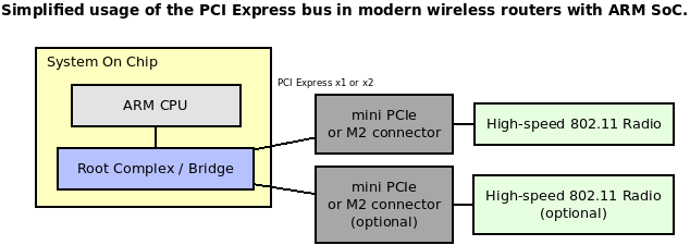
PCI and PCI Express
PCI 與 PCI Express
The original PCI bus was parallel with a lot of contacts and is currently obsolete. I will not focus on the obsolete PCI bus.
最初的 PCI 總線是并行的,有大量的連接點,目前已經過時。我不會關注這種過時的 PCI 總線。
Modern and faster PCIe bus uses single or multiple (1 - 16) pairs of differential wires (lanes, one pair for TX, and one for RX). You can tell the number of differential lines by the bus name, x1, x4, and x16. More lanes give a bigger throughput. Another difference between the PCI Express bus and the older PCI is the bus topology; PCI uses a shared parallel bus architecture. PCI Express is based on point - to - point topology, with separate serial links connecting every device to the root complex controller that can be integrated into the CPU. The PCI host and all devices share a common set of address, data, and control lines. You can read an excellent architecture explanation in this Wikipedia article.
現代且速度更快的 PCIe 總線使用單個或多個(1 - 16)對差分線(通道,一對用于 TX,一對用于 RX)。您可以通過總線名稱(如 x1、x4 和 x16)來判斷差分線的數量。通道越多,吞吐量越大。PCI Express 總線與舊的 PCI 總線之間的另一個區別是總線拓撲結構;PCI 使用共享并行總線架構,而 PCI Express 基于點對點拓撲,通過單獨的串行鏈路將每個設備連接到可以集成到 CPU 中的根復合體控制器。PCI 主機和所有設備共享一組公共的地址、數據和控制線。您可以在 這個 Wikipedia 文章中閱讀到一個優秀的架構解釋。
From the typical driver’s point of view, there is no difference between PCI and PCI Express. All differences are handled by the hardware and lower bus drivers of the Linux kernel. For the driver developer, API is the same.
從典型驅動程序的角度來看,PCI 和 PCI Express 之間沒有區別。所有區別都由硬件和 Linux 內核的低級總線驅動程序處理。對于驅動程序開發者來說,API 是相同的。
Linux PCI subsystem
Linux PCI 子系統
The operating system PCI subsystem reflects the actual hardware configuration and interconnections. There might be multiple PCI buses and multiple devices on those buses. Every bus and device is assigned a unique number, which allows identifying each module. Also, a PCI device might have different “functions” or “endpoints.” All those endpoints are also numbered. The full system path to the device might look like this: ::
操作系統中的 PCI 子系統反映了實際的硬件配置和連接關系。可能存在多個 PCI 總線以及這些總線上的多個設備。每個總線和設備都被分配了一個唯一的編號,用于識別每個模塊。此外,PCI 設備可能具有不同的“功能”或“端點”,這些端點也被編號。設備的完整系統路徑可能如下所示:<總線編號>:<設備編號>:<功能編號>
Additionally, every PCI device contains factory - programmed Vendor and Device IDs. These IDs are also unique and assigned by the PCI regulatory consortium. The Linux kernel can properly identify a device and load the proper driver using these IDs. Of course, every driver should have ID verification routines.
此外,每個 PCI 設備都包含工廠編程的供應商 ID 和設備 ID。這些 ID 也是唯一的,由 PCI 管理協會 分配。Linux 內核可以利用這些 ID 正確識別設備并加載相應的驅動程序。當然,每個驅動程序都應具備 ID 驗證功能。
The primary userspace utility is lspci This command can show a lot of useful information. Run this command with “-nn” argument to get all devices with IDs.
主要的用戶空間工具是 lspci,該命令可以顯示大量有用信息。使用“-nn”參數運行該命令,可以獲取所有帶有 ID 的設備信息。
[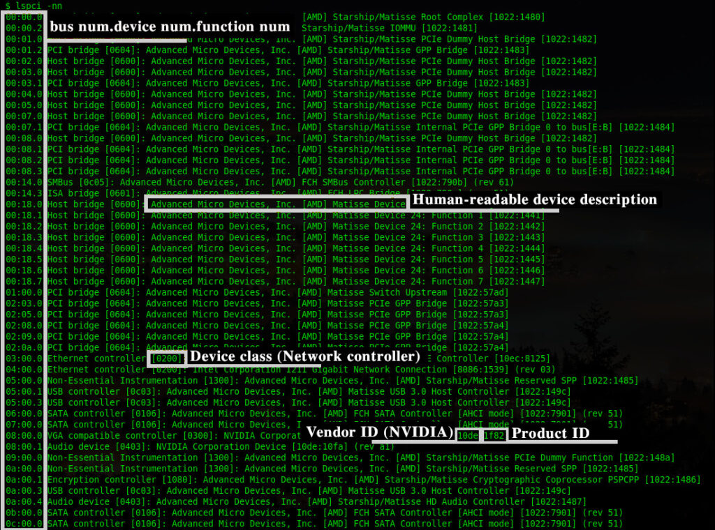
You can see many internal PCIe devices here, bridges, USB controllers, Audio and Network controllers, etc. All this information can be obtained manually from the sysfs:
您可以在此處看到許多內部 PCIe 設備,如橋接器、USB 控制器、音頻控制器和網絡控制器等。所有這些信息也可以手動從 sysfs 中獲取:
ls -la /sys/bus/pci/devices
lrwxrwxrwx 1 root root 0 Dec 21 14:05 0000:00:00.0 -> …/…/…/devices/pci0000:00/0000:00:00.0
lrwxrwxrwx 1 root root 0 Dec 21 14:05 0000:00:00.2 -> …/…/…/devices/pci0000:00/0000:00:00.2
lrwxrwxrwx 1 root root 0 Dec 21 14:05 0000:00:01.0 -> …/…/…/devices/pci0000:00/0000:00:01.0
lrwxrwxrwx 1 root root 0 Dec 21 14:05 0000:00:01.2 -> …/…/…/devices/pci0000:00/0000:00:01.2…
The human - readable strings are not taken from the hardware. This is a local database of the lspci: /usr/share/hwdata/pci.id You can always find the latest PCI ID database here: The PCI ID Repository Or you can check the Vendor ID here: Member Companies | PCI-SIG
這些可讀的字符串并非來自硬件,而是來自 lspci 的本地數據庫:/usr/share/hwdata/pci.id。您始終可以在以下位置找到最新的 PCI ID 數據庫:PCI ID 數據庫。您也可以在此處查看供應商 ID:PCI-SIG 會員公司
The Linux kernel assigns special memory regions, “Base Address Registers” (BARs), to communicate with the hardware. These memory addresses (and region length) are written to the PCI controller hardware during the system boot. You can find something like this In dmesg:
Linux 內核分配了特殊的內存區域,“基地址寄存器”(BARs),用于與硬件通信。這些內存地址(以及區域長度)在系統啟動時寫入 PCI 控制器硬件。您可以在 dmesg 中找到類似以下內容:
[ 0.959296] pci_bus 0001:00: root bus resource [bus 00 - ff]
[ 0.964853] pci_bus 0001:00: root bus resource [io 0x10000 - 0x1ffff] (bus address [0x0000 - 0xffff])
[ 0.973943] pci_bus 0001:00: root bus resource [mem 0x4840000000 - 0x487fffffff] (bus address [0x40000000 - 0x7fffffff])
[ 0.999755] pci 0001:00:00.0: BAR 14: assigned [mem 0x4840000000 - 0x48402fffff]
[ 1.007107] pci 0001:00:00.0: BAR 6: assigned [mem 0x4840300000 - 0x48403007ff pref]
[ 1.014769] pci 0001:01:00.0: BAR 0: assigned [mem 0x4840000000 - 0x48401fffff 64bit]
[ 1.022579] pci 0001:01:00.0: BAR 6: assigned [mem 0x4840200000 - 0x484020ffff pref]
[ 1.030265] pci 0001:00:00.0: PCI bridge to [bus 01 - ff]
[ 1.035563] pci 0001:00:00.0: bridge window [mem 0x4840000000 - 0x48402fffff]
There is no way to determine installed PCI hardware. So the bus must be enumerated. Bus enumeration is performed by attempting to read the vendor ID and device ID (VID/DID) register for each combination of the bus number and device number at the device’s function #0.
無法確定已安裝的 PCI 硬件,因此必須對總線進行枚舉。總線枚舉是通過嘗試讀取每個總線編號和設備編號組合的設備功能 #0 處的供應商 ID 和設備 ID(VID/DID)寄存器來完成的。
The kernel can call the corresponding driver during the enumeration stage with a compatible VID/PID pair. Some devices (like PCI bridges) might be statically described in the device tree in an embedded system. The static hardware configuration is supported with “platform drivers”.
在枚舉階段,內核可以根據兼容的 VID/PID 對調用相應的驅動程序。某些設備(如 PCI 橋接器)可能在嵌入式系統中的設備樹中靜態描述。靜態硬件配置由“平臺驅動程序”支持。
Every PCI compliant device should implement a basic set of register – configuration registers. The Linux kernel attempts to read these registers to identify and properly configure the device. All these registers are mapped to the memory and available for the driver developer for reading and writing.
每個符合 PCI 規范的設備都應實現一組基本寄存器——配置寄存器。Linux 內核嘗試讀取這些寄存器以識別和正確配置設備。所有這些寄存器都映射到內存中,可供驅動程序開發者讀取和寫入。
The first 64 bytes of the registers are mandatory and should be implemented (by the hardware vendor) in any case.
無論如何,硬件供應商都必須實現寄存器的前 64 字節。
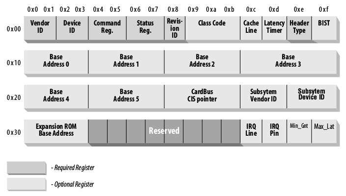
The optional registers may contain zero values if there is nothing to provide from the hardware.
如果硬件沒有提供任何內容,則可選寄存器可以包含零值。
Please note that byte order is always little - endian. This might be important if you are working on some big - endian system.
請注意,字節順序始終是小端模式。如果您正在處理某些大端模式的系統,這可能很重要。
Let’s dig into some registers deeply.
讓我們深入研究一些寄存器。
Vendor ID and Device ID are already well known and should contain valid identifiers of the hardware vendor.
供應商 ID 和 設備 ID 已廣為人知,應包含硬件供應商的有效標識符。
Command registers define some capabilities. The operating system initializes these bits.
命令 寄存器定義了一些功能。操作系統會初始化這些位。
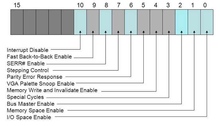
Status register holds different events of the PCI bus and is filled by the hardware.
狀態 寄存器保存了 PCI 總線的不同事件,由硬件填充。
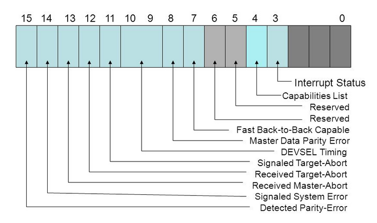
Class code defines a class of the device (Network adapter, for example).
類別代碼 定義了設備的類別(例如網絡適配器)。
Base Address Registers – “BAR” registers filled by the Linux kernel and used for the IO operations.
基地址寄存器 – 由 Linux 內核填充的“BAR”寄存器,用于 I/O 操作。
Subsystem Vendor ID and Subsystem Device ID – helps to differentiate specific board/device model. This is is optional, of course.
子系統供應商 ID 和 子系統設備 ID – 有助于區分特定的板卡/設備型號。當然,這是可選的。
The Linux kernel PCI implementation can be found in the kernel source tree drivers/pci directory. For driver developers kernel provides a header file include/linux/pci.h. Here you can find all the required structures and functions.
Linux 內核的 PCI 實現在內核源代碼樹的 drivers/pci 目錄中。對于驅動程序開發者,內核提供了一個頭文件 include/linux/pci.h,其中包含了所有必需的結構和函數。
The main PCI driver structure is struct pci_dev. This is quite a big structure representing an actual device and can be used for the register’s access and IO operations. Typically you don’t need to remember all fields of the structure, only basic concepts.
主要的 PCI 驅動程序結構是 struct pci_dev。這是一個相當大的結構,用于表示實際的設備,并可用于寄存器訪問和 I/O 操作。通常,您不需要記住該結構的所有字段,只需了解基本概念即可。
PCI driver entry point is struct pci_driver. The driver developer should initialize this structure (set callbacks) and pass it to the kernel.
PCI 驅動程序的入口點是 struct pci_driver。驅動程序開發者應初始化此結構(設置回調函數)并將其傳遞給內核。
struct pci_driver {struct list_head node;const char *name;const struct pci_device_id *id_table; /* Must be non - NULL for probe to be called */int (*probe)(struct pci_dev *dev, const struct pci_device_id *id); /* New device inserted */void (*remove)(struct pci_dev *dev); /* Device removed (NULL if not a hot - plug capable driver) */int (*suspend)(struct pci_dev *dev, pm_message_t state); /* Device suspended */int (*resume)(struct pci_dev *dev); /* Device woken up */void (*shutdown)(struct pci_dev *dev);int (*sriov_configure)(struct pci_dev *dev, int num_vfs); /* On PF */const struct pci_error_handlers *err_handler;const struct attribute_group **groups;struct device_driver driver;struct pci_dynids dynids;
};
The structure field “id_table” should be initialized with the IDs array. Those IDs define compatible Vendor and Product IDs for devices. You can set here multiple pairs of VID/PID if your driver supports multiple devices. For example, declare support of VID = 0F1F + PID = 0F0E, and VID = 0F2F + PID = 0F0D:
結構字段“id_table”應使用 ID 數組初始化。這些 ID 定義了設備兼容的供應商 ID 和產品 ID。如果您的驅動程序支持多個設備,可以在此處設置多個 VID/PID 對。例如,聲明支持 VID = 0F1F + PID = 0F0E 和 VID = 0F2F + PID = 0F0D:
static struct pci_device_id my_driver_id_table[] = {{ PCI_DEVICE(0x0F1F, 0x0F0E) },{ PCI_DEVICE(0x0F2F, 0x0F0D) },{0,}
};
It’s important to end this array with a single zero value.
以單個零值結束此數組非常重要。
Most drivers should export this table using MODULE_DEVICE_TABLE(pci, ...).
大多數驅動程序應使用 MODULE_DEVICE_TABLE(pci, ...) 導出此表。
This macro is doing a few important things. If your driver is built - in and compiled with the kernel, then the driver information (device IDs table) will be statically integrated into the global devices table. This allows the kernel to run your driver automatically when compatible hardware is found. If your driver is built as a separate module, then the device table can be extracted with depmod utility. This information is added to a cache and automatically loads your driver kernel object when compatible hardware is found.
此宏執行了一些重要的操作。如果您的驅動程序是內置的,并且與內核一起編譯,則驅動程序信息(設備 ID 表)將靜態集成到全局設備表中。這使得內核可以在找到兼容硬件時自動運行您的驅動程序。如果您的驅動程序是作為獨立模塊構建的,則可以使用 depmod 工具提取設備表。此信息將添加到緩存中,并在找到兼容硬件時自動加載您的驅動程序內核對象。
Other important fields of the struct pci_driver are:
struct pci_driver 的其他重要字段包括:
.name – unique driver name, this string will be displayed in /sys/bus/pci/drivers
.name – 唯一的驅動程序名稱,該字符串將顯示在 /sys/bus/pci/drivers 中
.probe – A callback function called by the kernel after the driver registration.
.probe – 在驅動程序注冊后由內核調用的回調函數。
.remove – A callback function called by the kernel during the driver unloading.
.remove – 在驅動程序卸載期間由內核調用的回調函數。
.suspend – A callback function called by kernel when the system is going to suspend mode.
.suspend – 在系統進入掛起模式時由內核調用的回調函數。
.resume – A callback function called when the system resumes after the suspend mode.
.resume – 在系統從掛起模式恢復時調用的回調函數。
Configured pci_driver should be registered and unregistered during the driver module loading and unloading. This allows the kernel to run your driver.
在驅動程序模塊加載和卸載期間,應注冊和注銷已配置的 pci_driver。這使得內核可以運行您的驅動程序。
pci_register_driver(struct pci_driver *);
pci_unregister_driver(struct pci_driver *);
Device access
設備訪問
To access PCI configuration registers kernel provides a set of functions:
為了訪問 PCI 配置寄存器,內核提供了一組函數:
int pci_read_config_byte(const struct pci_dev *dev, int where, u8 *val);
int pci_read_config_word(const struct pci_dev *dev, int where, u16 *val);
int pci_read_config_dword(const struct pci_dev *dev, int where, u32 *val);
int pci_write_config_byte(const struct pci_dev *dev, int where, u8 val);
int pci_write_config_word(const struct pci_dev *dev, int where, u16 val);
int pci_write_config_dword(const struct pci_dev *dev, int where, u32 val);
You can read and write 8, 16, and 32 - bit data.
您可以讀取和寫入 8 位、16 位和 32 位數據。
The argument “where” specifies the actual register offset. All accessible values are defined in linux/pci_regs.h
參數“where”指定實際的寄存器偏移量。所有可訪問的值都在 linux/pci_regs.h 中定義。
For example, read PCI device Vendor ID and Product ID:
例如,讀取 PCI 設備的 供應商 ID 和 產品 ID:
#include <linux/pci.h>u16 vendor, device, revision;pci_read_config_word(dev, PCI_VENDOR_ID, &vendor);
pci_read_config_word(dev, PCI_DEVICE_ID, &device);
Read the “Interrupt state” of the Status register:
讀取 狀態 寄存器的“中斷狀態”:
#include <linux/pci.h>u16 status_reg;pci_read_config_word(dev, PCI_STATUS, &status_reg);/* Check the bit 3 */
if ((status_reg >> 3) & 0x1) {printk("Interrupt bit is set\n");
} else {printk("Interrupt bit is not set\n");
}
Sure, the kernel has many other functions, but we will not discuss them there.
當然,內核還有許多其他函數,但在這里我們不會討論它們。
Actual device control and data communication is made through the mapped memory (BARs). It’s a little bit tricky. Of course, it’s just a memory region(s). What to read and write is depends on the actual hardware. It’s required to get actual offsets, data types, and “magic” numbers somewhere. Typically this is done through the reverse engineering of the Windows driver. But this is outside the scope of this article. Sometimes hardware vendors are kind enough to share their protocols and specifications.
實際的設備控制和數據通信是通過映射的內存(BARs)完成的。這有點棘手。當然,它只是一個內存區域。讀取和寫入什么內容取決于實際的硬件。需要從某處獲取實際的偏移量、數據類型和“魔法”數字。通常,這是通過逆向工程 Windows 驅動程序完成的。但這超出了本文的范圍。有時,硬件供應商會慷慨地分享他們的協議和規格。
To access the device memory, we need to request the memory region, start and stop offsets and map this memory region to some local pointer.
為了訪問設備內存,我們需要請求內存區域、起始和結束偏移量,并將該內存區域映射到某個本地指針。
#include <linux/pci.h>int bar;
unsigned long mmio_start, mmio_len;
u8 __iomem *hwmem; /* Memory pointer for the I/O operations */struct pci_dev *pdev; /* Initialized pci_dev */.../* Request the I/O resource */
bar = pci_select_bars(pdev, IORESOURCE_MEM);/* "enable" device memory */
pci_enable_device_mem(pdev);/* Request the memory region */
pci_request_region(pdev, bar, "My PCI driver");/* Get the start and stop memory positions */
mmio_start = pci_resource_start(pdev, 0);
mmio_len = pci_resource_len(pdev, 0);/* map provided resource to the local memory pointer */
hwmem = ioremap(mmio_start, mmio_len);
Now it’s possible to use hwmem to read and write from/to the device. The only correct way is to use special kernel routines. The data can be read and written in the 8, 16, and 32 - bit chunks.
現在可以使用 hwmem 從設備讀取和寫入數據。唯一正確的方法是使用特殊的內核例程。數據可以以 8 位、16 位和 32 位塊的形式讀取和寫入。
void iowrite8(u8 b, void __iomem *addr);
void iowrite16(u16 b, void __iomem *addr);
void iowrite32(u16 b, void __iomem *addr);unsigned int ioread8(void __iomem *addr);
unsigned int ioread16(void __iomem *addr);
unsigned int ioread32(void __iomem *addr);
You might note that there is an alternatively IO API that can be found in some drivers.
您可能會注意到,在某些驅動程序中可以找到另一種 IO API。
#include <linux/io.h>unsigned readb(address);
unsigned readw(address);
unsigned readl(address);
void writeb(unsigned value, address);
void writew(unsigned value, address);
void writel(unsigned value, address);
On x86 and ARM platforms, ioreadX/iowriteX functions are just inline wrappers around these readX/writeX functions. But for better portability and compatibility, it’s highly recommended to use io* functions.
在 x86 和 ARM 平臺上,ioreadX/iowriteX 函數只是這些 readX/writeX 函數的內聯包裝器。但為了更好的可移植性和兼容性,強烈建議使用 io* 函數。
PCI DMA
PCI 直接內存訪問
The high - performance device supports Direct Memory Access. This is implemented with bus mastering. Buse mastering is the capability of devices on the PCI bus to take control of the bus and perform transfers to the mapped memory directly.
高性能設備支持直接內存訪問(DMA)。這是通過總線主控實現的。總線主控是指 PCI 總線上的設備能夠接管總線,并直接對映射的內存執行傳輸。
Bus mastering (if supported) can be enabled and disabled with the following functions:
如果支持,可以使用以下函數啟用和禁用總線主控:
void pci_set_master(struct pci_dev *dev);
void pci_clear_master(struct pci_dev *dev);
PCI interrupts
PCI 中斷
Interrupt handling is critical in device drivers. Hardware may generate an interrupt on data reception event, error, state changes, and so on. All interrupts should be handled most optimally.
中斷處理在設備驅動程序中至關重要。硬件可能會在數據接收事件、錯誤、狀態變化等情況下生成中斷。所有中斷都應盡可能高效地處理。
There are two types of PCI interrupts:
有兩種類型的 PCI 中斷:
-
Pin - based (INTx) interrupts, an old and classic way
-
MSI/MSI - X interrupts, modern and more optimal way, introduced in PCI 2.2
-
基于引腳(INTx) 的中斷,一種古老而經典的方式
-
MSI/MSI - X 中斷,一種現代且更優的方式,引入于 PCI 2.2
It’s highly recommended to use MSI interrupts when possible. There are a few reasons why using MSIs can be advantageous over traditional pin - based interrupts.
如果可能,強烈建議使用 MSI 中斷。使用 MSI 而非傳統的基于引腳的中斷有幾個優點。
Pin - based PCI interrupts are often shared amongst several devices. To support this, the kernel must call each interrupt handler associated with an interrupt, which leads to reduced performance for the system. MSIs are never shared, so this problem cannot arise.
基于引腳的 PCI 中斷通常由多個設備共享。為了支持這一點,內核必須調用與中斷相關聯的每個中斷處理程序,這會導致系統性能下降。MSI 永不共享,因此不會出現此問題。
When a device writes data to memory, then raises a pin - based interrupt, the interrupt may arrive before all the data has arrived in memory (this becomes more likely with devices behind PCI - PCI bridges). The interrupt handler must read a register on the device that raised the interrupt to ensure that all the data has arrived in memory. PCI transaction ordering rules require that all the data arrive in memory before the value may be returned from the register. Using MSI’s avoids this problem as the interrupt - generating write cannot pass the data writes, so by the time the interrupt is raised, the driver knows that all the data has arrived in memory.
當設備將數據寫入內存,然后引發基于引腳的中斷時,中斷可能會在所有數據到達內存之前到達(在 PCI - PCI 橋接器后面的設備中,這種情況更有可能發生)。中斷處理程序必須讀取引發中斷的設備上的一個寄存器,以確保所有數據都已到達內存。PCI 事務排序規則要求所有數據必須在返回寄存器的值之前到達內存。使用 MSI 可以避免此問題,因為引發中斷的寫操作不能超越數據寫操作,因此當引發中斷時,驅動程序知道所有數據都已到達內存。
Please note that not all machines support MSIs correctly.
請注意,并非所有機器都能正確支持 MSI。
You can find information about currently allocated interrupts in /proc/interrupts This information contains interrupt spreads over the CPU cores and interrupts types (MSI or pin - based). Typically interrupts are dynamically set for the CPU cores. A special daemon tries to spread interrupts in the most optimal way on some systems.
您可以在 /proc/interrupts 中找到有關當前已分配中斷的信息。這些信息包括中斷在 CPU 核心上的分布以及中斷類型(MSI 或基于引腳)。通常,中斷會動態分配給 CPU 核心。在某些系統上,一個特殊的守護進程會嘗試以最優化的方式分配中斷。
Also, you can manually select the CPU core for the selected interrupt. This might be helpful in some fine - tuning situations. The core assignment can be done via the SMP affinity mechanism. Just select required cores (in a binary pattern) and send this value (as HEX number) to /proc/irq/X/smp_affinity, where X is the interrupt number. For example, put IRQ 44 to the first and third cores (set bits 0 and 2, from left to right):
此外,您還可以手動為選定的中斷選擇 CPU 核心。在某些微調情況下,這可能會有所幫助。可以通過 SMP 親和性 機制完成核心分配。只需選擇所需的核心(以二進制模式),并將該值(以十六進制數字表示)發送到 /proc/irq/X/smp_affinity,其中 X 是中斷編號。例如,將 IRQ 44 分配給第一和第三個核心(設置第 0 位和第 2 位,從左到右):
echo 5 > /proc/irq/44/smp_affinity
Now let’s see how to use both types of interrupts.
現在讓我們看看如何使用這兩種類型的中斷。
INTx interrupts
INTx 中斷
The classic pin - based interrupt can be requested with request_threaded_irq() and request_irq()
經典的基于引腳的中斷可以通過 request_threaded_irq() 和 request_irq() 請求。
int request_threaded_irq( unsigned int irq,irq_handler_t handler,irq_handler_t thread_fn,unsigned long irqflags,const char * devname,void * dev_id);int request_irq( unsigned int irq,irqreturn_t handler,unsigned long irqflags,const char *devname,void *dev_id);
For the new drivers, it’s recommended to use request_threaded_irq()
對于新的驅動程序,建議使用 request_threaded_irq()
The first parameter, irq specifies the interrupt number to allocate. For some devices, for example, legacy PC devices such as the system timer or keyboard, this value is typically hard - coded. It is probed or otherwise determined programmatically and dynamically for most other devices.
第一個參數 irq 指定要分配的中斷編號。對于某些設備,例如系統時鐘或鍵盤等傳統的 PC 設備,此值通常是硬編碼的。對于大多數其他設備,它會通過探測或其他方式動態地、程序化地確定。
The second parameter, handler is the function to be called when the IRQ occurs.
第二個參數 handler 是在發生 IRQ 時要調用的函數。
thread_fn – Function called from the IRQ handler thread. If NULL – no IRQ thread is created.
thread_fn – 在 IRQ 處理程序線程中調用的函數。如果為 NULL,則不創建 IRQ 線程。
irqflags – Interrupt type flags; Possible values can be found here.
irqflags – 中斷類型標志;可能的值可以在 這里 找到。
dev_name – The string passed to request_irq is used in /proc/interrupts to show the owner of the interrupt.
dev_name – 傳遞給 request_irq 的字符串用于在 /proc/interrupts 中顯示中斷的所有者。
dev_id – This pointer is used for shared interrupt lines. It is a unique identifier used when the interrupt line is freed, and the driver may also use that to point to its own private data area (to identify which device is interrupting).
dev_id – 此指針用于共享中斷線。它是一個唯一的標識符,用于在釋放中斷線時使用,驅動程序也可以用它指向自己的私有數據區域(以識別哪個設備正在中斷)。
In the end, all requested IRQs should be released with free_irq()
最終,所有請求的 IRQ 都應通過 free_irq() 釋放。
void free_irq ( unsigned int irq, void * dev_id);
A simple example, install and use interrupt #42:
一個簡單示例,安裝并使用中斷 #42:
static irqreturn_t sample_irq(int irq, void *dev_id)
{printk("IRQ %d\n", irq);return IRQ_HANDLED;
}...if (request_irq(42, test_irq, 0, "test_irq", 0) < 0) {return -1;
}
MSI interrupts
MSI 中斷
In the case of MSI/MSIX interrupts, everything is almost the same, but it’s required to tell the PCI subsystem that we want to use MSI/MSIX interrupts.
在 MSI/MSIX 中斷的情況下,幾乎所有內容都幾乎相同,但需要告訴 PCI 子系統我們想使用 MSI/MSIX 中斷。
Use the following function:
使用以下函數:
int pci_alloc_irq_vectors(struct pci_dev *dev, unsigned int min_vecs, unsigned int max_vecs, unsigned int flags);
This function allocates up to max_vecs interrupt vectors for a PCI device. It returns the number of vectors allocated or a negative error.
此函數為 PCI 設備分配多達 max_vecs 個中斷向量。它返回分配的向量數量或一個負錯誤值。
The flags argument is used to specify which type of interrupt can be used by the device and the driver (PCI_IRQ_LEGACY, PCI_IRQ_MSI, PCI_IRQ_MSIX). A convenient short - hand (PCI_IRQ_ALL_TYPES) is also available to ask for any possible kind of interrupt. If the PCI_IRQ_AFFINITY flag is set, pci_alloc_irq_vectors() will spread the interrupts around the available CPUs.
參數 flags 用于指定設備和驅動程序可以使用的中斷類型(PCI_IRQ_LEGACY、PCI_IRQ_MSI、PCI_IRQ_MSIX)。還可以使用一個方便的簡寫(PCI_IRQ_ALL_TYPES)來請求任何可能的中斷類型。如果設置了 PCI_IRQ_AFFINITY 標志,pci_alloc_irq_vectors() 將在可用的 CPU 之間分配中斷。
Of course, interrupt type (MSI/MSIX) and the number of MSI interrupts depend on your hardware.
當然,中斷類型(MSI/MSIX)和 MSI 中斷的數量取決于您的硬件。
Free the allocated resources with:
使用以下函數釋放分配的資源:
void pci_free_irq_vectors(struct pci_dev *dev);
PCI driver skeleton
PCI 驅動程序框架
I think it’s enough with boring theory. This is an example of the PCI device driver. This driver can load and register for specified VID/PID pairs. Some basic operations (config registers read, memory read/write) are performed.
我認為理論部分已經足夠了。這是一個 PCI 設備驅動程序的示例。該驅動程序可以加載并為指定的 VID/PID 對注冊。它執行了一些基本操作(配置寄存器讀取、內存讀寫)。
/* Sample Linux PCI device driver */#include <linux/init.h>
#include <linux/module.h>
#include <linux/pci.h>#define MY_DRIVER "my_pci_driver"/* This sample driver supports device with VID = 0x010F, and PID = 0x0F0E*/
static struct pci_device_id my_driver_id_table[] = {{ PCI_DEVICE(0x010F, 0x0F0E) },{0,}
};MODULE_DEVICE_TABLE(pci, my_driver_id_table);static int my_driver_probe(struct pci_dev *pdev, const struct pci_device_id *ent);
static void my_driver_remove(struct pci_dev *pdev);/* Driver registration structure */
static struct pci_driver my_driver = {.name = MY_DRIVER,.id_table = my_driver_id_table,.probe = my_driver_probe,.remove = my_driver_remove
};/* This is a "private" data structure */
/* You can store there any data that should be passed between driver's functions */
struct my_driver_priv {u8 __iomem *hwmem;
};/* */static int __init mypci_driver_init(void)
{/* Register new PCI driver */return pci_register_driver(&my_driver);
}static void __exit mypci_driver_exit(void)
{/* Unregister */pci_unregister_driver(&my_driver);
}void release_device(struct pci_dev *pdev)
{/* Disable IRQ #42*/free_irq(42, pdev);/* Free memory region */pci_release_region(pdev, pci_select_bars(pdev, IORESOURCE_MEM));/* And disable device */pci_disable_device(pdev);
}/* */static irqreturn_t irq_handler(int irq, void *cookie)
{(void) cookie;printk("Handle IRQ #%d\n", irq);return IRQ_HANDLED;
}/* Reqest interrupt and setup handler */
int set_interrupts(struct pci_dev *pdev)
{/* We want MSI interrupt, 3 lines (just an example) */int ret = pci_alloc_irq_vectors(pdev, 3, 3, PCI_IRQ_MSI);if (ret < 0) {return ret;}/* Request IRQ #42 */return request_threaded_irq(42, irq_handler, NULL, 0, "TEST IRQ", pdev);
}/* Write some data to the device */
void write_sample_data(struct pci_dev *pdev)
{int data_to_write = 0xDEADBEEF; /* Just a random trash */struct my_driver_priv *drv_priv = (struct my_driver_priv *) pci_get_drvdata(pdev);if (!drv_priv) {return;}/* Write 32 - bit data to the device memory */iowrite32(data_to_write, drv_priv->hwmem);
}/* This function is called by the kernel */
static int my_driver_probe(struct pci_dev *pdev, const struct pci_device_id *ent)
{int bar, err;u16 vendor, device;unsigned long mmio_start, mmio_len;struct my_driver_priv *drv_priv;/* Let's read data from the PCI device configuration registers */pci_read_config_word(pdev, PCI_VENDOR_ID, &vendor);pci_read_config_word(pdev, PCI_DEVICE_ID, &device);printk(KERN_INFO "Device vid: 0x%X pid: 0x%X\n", vendor, device);/* Request IO BAR */bar = pci_select_bars(pdev, IORESOURCE_MEM);/* Enable device memory */err = pci_enable_device_mem(pdev);if (err) {return err;}/* Request memory region for the BAR */err = pci_request_region(pdev, bar, MY_DRIVER);if (err) {pci_disable_device(pdev);return err;}/* Get start and stop memory offsets */mmio_start = pci_resource_start(pdev, 0);mmio_len = pci_resource_len(pdev, 0);/* Allocate memory for the driver private data */drv_priv = kzalloc(sizeof(struct my_driver_priv), GFP_KERNEL);if (!drv_priv) {release_device(pdev);return -ENOMEM;}/* Remap BAR to the local pointer */drv_priv->hwmem = ioremap(mmio_start, mmio_len);if (!drv_priv->hwmem) {release_device(pdev);return -EIO;}/* Set driver private data *//* Now we can access mapped "hwmem" from the any driver's function */pci_set_drvdata(pdev, drv_priv);write_sample_data(pdev);return set_interrupts(pdev);
}/* Clean up */
static void my_driver_remove(struct pci_dev *pdev)
{struct my_driver_priv *drv_priv = pci_get_drvdata(pdev);if (drv_priv) {if (drv_priv->hwmem) {iounmap(drv_priv->hwmem);}pci_free_irq_vectors(pdev);kfree(drv_priv);}release_device(pdev);
}MODULE_LICENSE("GPL");
MODULE_AUTHOR("OlegKutkov <contact@olegkutkov.me>");
MODULE_DESCRIPTION("Test PCI driver");
MODULE_VERSION("0.1");module_init(mypci_driver_init);
module_exit(mypci_driver_exit);
And Makefile:
以及 Makefile:
BINARY   := test_pci_module
KERNEL   := /lib/modules/$(shell uname -r)/build
ARCH    := x86
C_FLAGS   := -Wall
KMOD_DIR  := $(shell pwd)OBJECTS := test_pci.occflags-y += $(C_FLAGS)obj-m += $(BINARY).o$(BINARY)-y := $(OBJECTS)$(BINARY).ko:make -C $(KERNEL) M=$(KMOD_DIR) modulesclean:rm -f $(BINARY).ko
Real - life example
實際案例
I worked in the Crimean Astrophysical observatory a few years ago and found a PCI interface board for 4 incremental linear or angular encoders. I decided to use this board, but there was no Linux driver. I contacted the vendor and proposed to them to write an open - source driver for Linux. They were kind enough and proposed the full documentation. This was a table with memory offsets and data sizes. Basically, at which offsets I can read sensor data and so on.
幾年前,我在克里米亞天體物理天文臺工作時,發現了一塊用于 4 個增量式線性或角編碼器的 PCI 接口板。我決定使用這塊板,但當時沒有 Linux 驅動程序。我聯系了供應商,建議他們為 Linux 編寫一個開源驅動程序。他們非常慷慨,提供了完整的文檔。那是一個包含內存偏移量和數據大小的表格。基本上,它告訴我可以在哪些偏移量處讀取傳感器數據等信息。
I wrote this driver. The driver uses a character device interface to interact with the user. It’s quite simple and might be a good example to start PCI driver development.
我編寫了 這個驅動程序。該驅動程序使用 字符設備 接口與用戶交互。它非常簡單,可能是開始 PCI 驅動程序開發的一個很好的例子。
via:
-
如何寫 Linux PCI 驅動 — The Linux Kernel documentation
https://www.kernel.org/doc/html/v6.15-rc1/translations/zh_CN/PCI/pci.html- How To Write Linux PCI Drivers — The Linux Kernel documentation
https://docs.kernel.org/PCI/pci.html
- How To Write Linux PCI Drivers — The Linux Kernel documentation
-
PCI Drivers - Linux Device Drivers, 3rd Edition [Book]
https://www.oreilly.com/library/view/linux-device-drivers/0596005903/ch12.html -
Writing a PCI device driver for Linux – Oleg Kutkov personal blog
https://olegkutkov.me/2021/01/07/writing-a-pci-device-driver-for-linux/ -
pcie tlp preparation in linux driver | Linux.org
https://www.linux.org/threads/pcie-tlp-preparation-in-linux-driver.45843/


深藍學院動力學kinodynamic A* 3D算法理論解讀(附C++代碼))


)

、date_add()、datediff() 詳解-文中有示例幫助理解)


)


