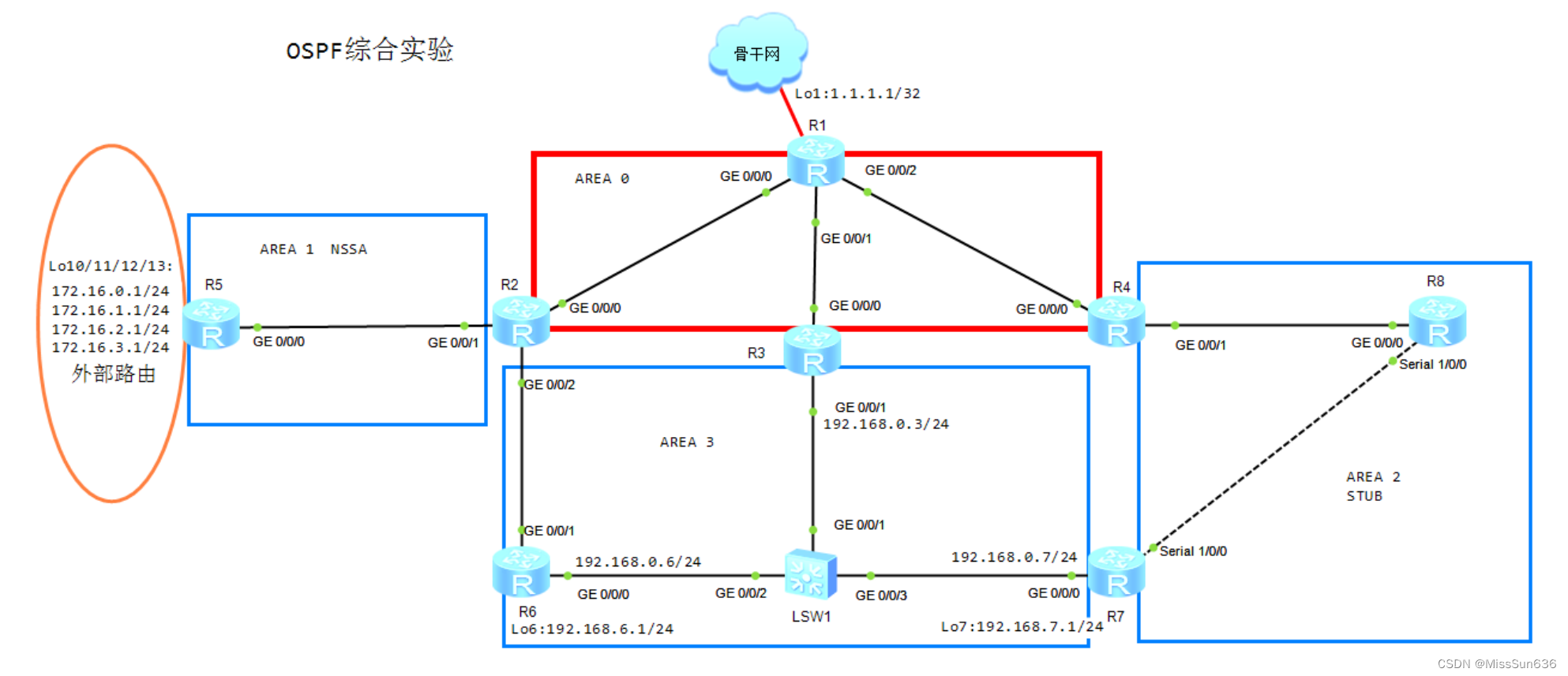
六、OSPF-2 綜合實驗 實驗拓撲 實驗需求及解法 1.設備名稱和部分IP地址已配置 2.所有設備運行OSPF,進程號為1 3.區域間路由匯總 4.外部路由匯總 5.下發默認路由 6. 虛鏈路
本實驗模擬OSPF綜合型網絡,按照以下需求完成實驗。 R3 :
interface GigabitEthernet0 / 0 / 1
ip address 192.168 .0 .3 255.255 .255 .0
#
R6 :
interface GigabitEthernet0 / 0 / 0
ip address 192.168 .0 .6 255.255 .255 .0
#
R7 :
interface GigabitEthernet0 / 0 / 0
ip address 192.168 .0 .7 255.255 .255 .0
2.1 手動設置Loobapck0的IP地址作為Router-id。 2.2 如圖所示將各接口劃入指定區域。ABR的Lo0劃入區域0。 2.3 所有network命令均使用0.0.0.0的通配符。 2.4 區域0啟用密文驗證,驗證方式為MD5,KEY-ID為1。 使用display命令可以查看到真實密碼為“spoto”(不包含引號)。 2.5 區域1配置為NSSA區域。 2.6 區域2配置為stub區域,并配置為完全末節. 2.7 區域 3 為普通區域。在 R3/6/7 之間強制選擇 R3 為 DR,沒有 BDR。 R1 :
ospf 1 router- id 10.0 .1 .1
area 0.0 .0 .0 authentication- mode md5 1 plain spotonetwork 10.0 .1 .1 0.0 .0 .0 network 10.0 .12 .1 0.0 .0 .0 network 10.0 .13 .1 0.0 .0 .0 network 10.0 .14 .1 0.0 .0 .0
#
R2 :
ospf 1 router- id 10.0 .2 .2
area 0.0 .0 .0 authentication- mode md5 1 plain spotonetwork 10.0 .2 .2 0.0 .0 .0 network 10.0 .12 .2 0.0 .0 .0
area 0.0 .0 .1 network 10.0 .25 .2 0.0 .0 .0 nssa
area 0.0 .0 .3 network 10.0 .26 .2 0.0 .0 .0
#
R3 :
ospf 1 router- id 10.0 .3 .3
area 0.0 .0 .0 authentication- mode md5 1 plain spotonetwork 10.0 .3 .3 0.0 .0 .0 network 10.0 .13 .3 0.0 .0 .0
area 0.0 .0 .3 network 192.168 .0 .3 0.0 .0 .0
#
R4 :
ospf 1 router- id 10.0 .4 .4
area 0.0 .0 .0 authentication- mode md5 1 plain spotonetwork 10.0 .4 .4 0.0 .0 .0 network 10.0 .14 .4 0.0 .0 .0
area 0.0 .0 .2 network 10.0 .48 .4 0.0 .0 .0 stub no- summary
#
R5 :
ospf 1 router- id 10.0 .5 .5
area 0.0 .0 .1 network 10.0 .5 .5 0.0 .0 .0 network 10.0 .25 .5 0.0 .0 .0 nssa
#
R6 :
ospf 1 router- id 10.0 .6 .6
area 0.0 .0 .3 network 10.0 .6 .6 0.0 .0 .0 network 10.0 .26 .6 0.0 .0 .0 network 192.168 .0 .6 0.0 .0 .0 network 192.168 .6 .1 0.0 .0 .0
interface GigabitEthernet0 / 0 / 0
ospf dr- priority 0
#
R7 :
ospf 1 router- id 10.0 .7 .7
area 0.0 .0 .2 network 10.0 .78 .7 0.0 .0 .0 stub
area 0.0 .0 .3 network 10.0 .7 .7 0.0 .0 .0 network 192.168 .0 .7 0.0 .0 .0 network 192.168 .7 .1 0.0 .0 .0
interface GigabitEthernet0 / 0 / 0
ospf dr- priority 0
#
R8 :
ospf 1 router- id 10.0 .8 .8
area 0.0 .0 .2 network 10.0 .8 .8 0.0 .0 .0 network 10.0 .48 .8 0.0 .0 .0 network 10.0 .78 .8 0.0 .0 .0 stub
3.1 在R6的Lo6口和R7的Lo7口上修改網絡類型,使得OSPF產生24位路由。 R6 :
interface LoopBack6
ospf network- type broadcast
R7 :
interface LoopBack7
ospf network- type broadcast
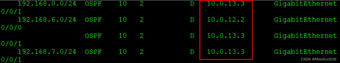
3.2 R1去往區域3的 192.168.0.0/24 192.168.6.0/24 192.168.7.0/24有R2和R3兩條可用路徑。 在R2上將這三條路由匯總為192.168.0.0/16,使得R1優先走R3去往區域3。 < R1 > dis ip routing- table protocol ospf
有10.0.13.2和10.0.13.3兩個可用下一跳 R2 :
ospf 1 router- id 10.0 .2 .2
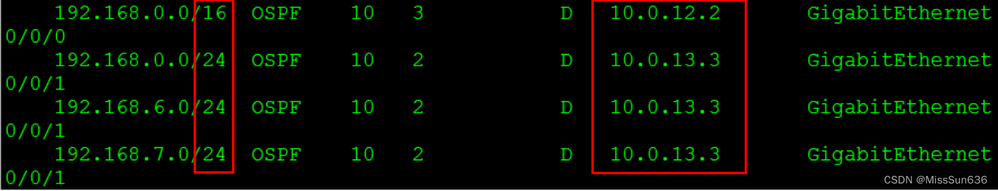
area 0.0 .0 .3 abr- summary 192.168 .0 .0 255.255 .0 .0
#再次查看R1 的路由表
< R1 > dis ip routing- table protocol ospf
根據最長匹配原則,會選擇10.0.13.3作為最佳下一跳。10.0.12.2成為備用下一跳。 R5上有四條外部路由如下: 172.16.0.1/24 172.16.1.1/24 172.16.2.1/24 172.16.3.1/24 R5將以上四條路由匯總為172.16.0.0/22,再發布到OSPF。 R5 :
ospf 1 router- id 10.0 .5 .5
import - route direct
asbr- summary 172.16 .0 .0 255.255 .252 .0
R1作為OSPF系統的總出口,上連骨干網。(使用Lo1模擬骨干網) 在R1上下發默認路由到OSPF系統內,使得所有設備可以訪問1.1.1.1。 R1 :
ospf 1 router- id 10.0 .1 .1
default - route- advertise always
解析:OSPF引入外部路由時,不能引入默認路由。只有使用命令default-route-advertise才能引入默認路由,且前提條件是本地必須有默認路由。加上always參數后,無論本地是否有默認路由,都可以直接下發默認路由。 在區域2中,R8需要高可靠性鏈路保障,完成以下需求: 6.1 將R8的S1/0/0接口cost值修改為65535。 使得R4作為主要鏈路,R7作為備份鏈路。 R8 :
interface Serial1 / 0 / 0
ospf cost 65535
6.2 R7與R3建立虛鏈路,使得R7成為ABR。 當R8-R4鏈路故障時,R8可以從R7接收到OSPF路由。 (提示:需要考慮需求2.4和2.6。) R3 :
ospf 1 router- id 10.0 .3 .3
area 0.0 .0 .3 vlink- peer 10.0 .7 .7
#
R7 :
ospf 1 router- id 10.0 .7 .7
area 0.0 .0 .3 vlink- peer 10.0 .3 .3
area 0.0 .0 .0 authentication- mode md5 1 plain spoto
在需求2.4中區域0需要啟用區域驗證。當R7通過Vlink進入區域0后,也需要啟用驗證。 area 0.0 .0 .2 stub no- summary
在需求2.6中要求配置為完全末節,此時R7成為區域2的ABR,也需要配置no-summary。 6.3 當R8-R4鏈路故障恢復時,需要快速建立鄰接關系: R4 :
interface GigabitEthernet0 / 0 / 1
ospf network- type p2p
ospf timer hello 3
R8 :
interface GigabitEthernet0 / 0 / 0
ospf network- type p2p
ospf timer hello 3


)


)


解決方案)


