1. Teleport 示例
ROS 服務的作用: 提供了一種同步、請求-響應的通信方式,用于執行那些需要即時獲取結果或狀態反饋的一次性操作或查詢。
Teleport 服務在 ROS 仿真(尤其是 Gazebo)和某些簡單機器人控制中扮演著瞬移機器人或對象的角色。
Teleport Service 是一個具體應用,它利用 ROS 服務機制來實現在仿真(或極少數簡單真實場景)中瞬間設置機器人/模型位置和朝向的功能,主要用于調試、測試和快速初始化。它是一個典型的 ROS 服務。
-
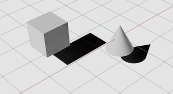
在 Isaac Sim 的示例中,打開 Isaac Examples?> ROS?> Teleport。此時,場景中會自動加載一個立方體和一個圓錐。
-
如果未打開 Action Graph 窗口,請通過菜單:Window > Visual Scripting > Action Graph
-
此時工作圖(graph)應只包含兩個節點:

-
On Playback Tick
-
ROS1 Teleport Service
-
-
要調用該服務,請在另一個終端中,加載 Isaac?Sim 的 ROS1 工作區,然后運行示例客戶端腳本:rosrun isaac_tutorials ros_service_client.py
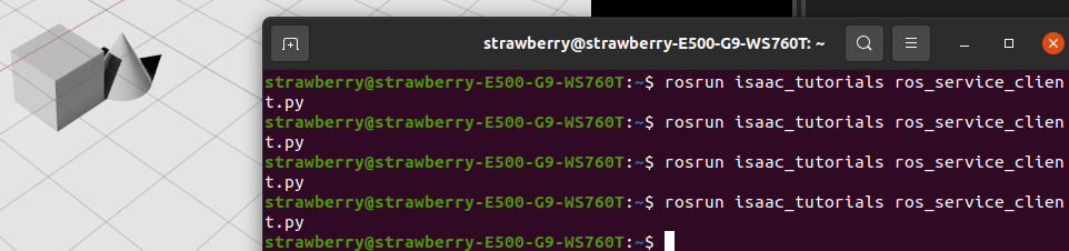
你會看到立方體和圓錐像中了瞬移咒一樣,每次都會跳到隨機的新位置。😉
Pose Teleport Service 消息定義
該服務使用一個自定義的 IsaacPose ROS Service 消息,定義文件位于:
<noetic_ws>/src/isaac_ros_messages/srv/IsaacPose.srv消息結構如下:
std_msgs/Header        header
string[]               names
geometry_msgs/Pose[]   poses
geometry_msgs/Twist[]  velocities
geometry_msgs/Vector3[] scales
-
names:一個字符串數組,包含要傳送對象的 prim 路徑,必須與場景中的路徑完全一致。
-
poses:一個
Pose數組,與names一一對應,指定每個對象的目標位置。 -
(可選)velocities 和 scales 可用于同時設置速度和縮放,但在本示例中未用到。
客戶端示例腳本
下面是示例中運行的客戶端腳本,位于:
<noetic_ws>/src/isaac_tutorials/scripts/ros_service_client.py
import rospy
import numpy as np
from isaac_ros_messages.srv import IsaacPose, IsaacPoseRequest
from geometry_msgs.msg import Posedef teleport_client(msg):rospy.wait_for_service("teleport")try:teleport = rospy.ServiceProxy("teleport", IsaacPose)teleport(msg)except rospy.ServiceException as e:print("Service call failed: %s" % e)# 隨機生成立方體的新位置
cube_pose = Pose()
cube_pose.position.x = np.random.uniform(-2, 2)
cube_pose.position.y = 0
cube_pose.position.z = 0
cube_pose.orientation.w = 1# 隨機生成圓錐的新位置
cone_pose = Pose()
cone_pose.position.x = 0
cone_pose.position.y = np.random.uniform(-2, 2)
cone_pose.position.z = 0
cone_pose.orientation.w = 1# 組裝服務請求
teleport_msg = IsaacPoseRequest()
teleport_msg.names = ["/World/Cube", "/World/Cone"]
teleport_msg.poses = [cone_pose, cube_pose]# 調用服務
teleport_client(teleport_msg)
2. ROS導航
學習目標
在本 ROS 示例中,我們將:
-
演示 Omniverse Isaac Sim 與 ROS Navigation 棧的集成。
-
使用地圖生成器(Occupancy Map Generator)。
2.1 前提條件
-
安裝 ROS Navigation 棧
在終端中運行:sudo apt-get install ros-$ROS_DISTRO-navigation這樣就能獲取所有核心的導航功能包了。
-
獲取示例所需包
本教程依賴以下三個 ROS 包,它們位于你的工作空間下的src/navigation/目錄中:-
carter_2dnav -
carter_description -
isaac_ros_navigation_goal
這些包分別包含:
-
啟動文件(launch files)
-
導航參數配置
-
機器人模型文件
確保你已經完成了 ROS 和 ROS?2 的安裝,且正確配置了 ROS 環境變量(例如
source /opt/ros/$ROS_DISTRO/setup.bash),并且src/navigation/已在你的ROS_PACKAGE_PATH中。 -
-
啟用 ROS 橋接并啟動 roscore
-
可選:如果你對 RTX 激光雷達(Lidar)傳感器的工作原理、相關節點,或如何獲取合成數據感興趣,可閱讀《RTX Lidar 傳感器原理與使用指南》,深入了解它們在導航中的應用。
2.2 ROS導航設置
下面是該 ROS Navigation 棧所需的主要話題及其消息類型,對應圖中的各個模塊:
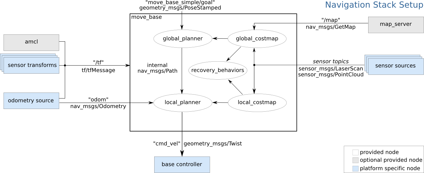
| ROS 話題 (Topic) | 消息類型 (Message Type) | 作用簡介 |
|---|---|---|
/tf | tf2_msgs/TFMessage | 發布各坐標系之間的變換,用于維護機器人在世界、里程計、傳感器等坐標系下的位置關系。 |
/odom | nav_msgs/Odometry | 發布機器人里程計信息,常由里程計源(輪速計/仿真/SLAM)產生,用于局部規劃。 |
/map | nav_msgs/OccupancyGrid | 發布全局柵格地圖(占據柵格),供全局規劃器(global_planner)做路徑搜索。 |
/scan | sensor_msgs/LaserScan | 發布激光雷達掃描數據,驅動本地/全局代價地圖(costmap)和避障模塊。 |
各模塊如何利用這些話題
-
/map&map_server→global_costmap→global_planner
全局地圖加載后,global_costmap將其轉成代價地圖,再由全局規劃器計算從起點到目標的粗略路徑。 -
/odom&/tf→ local_planner & local_costmap
局部代價地圖不斷融合里程計和雷達數據,為local_planner提供實時障礙物信息,生成可執行的局部路徑。 -
/scan→ global_costmap & local_costmap
激光數據同時更新全局和局部代價地圖,保證導航對新出現的障礙物能夠“眼觀六路、耳聽八方”。 -
tf2_msgs/TFMessage
/tf話題上廣播的坐標變換,讓各節點能夠把傳感器數據、位姿、路徑都正確地“放”到同一個世界坐標系下。
2.3 Carter_ROS Omnigraph 節點說明
在 Isaac Examples → ROS → Navigation 中加載倉庫場景(warehouse scenario)。
Graph 說明
-
展開 Carter_ROS,右鍵點擊 ActionGraph,選擇 Open Graph。圖中的控制部分就是經典的兩輪小車graph,重點看ros部分:
? -
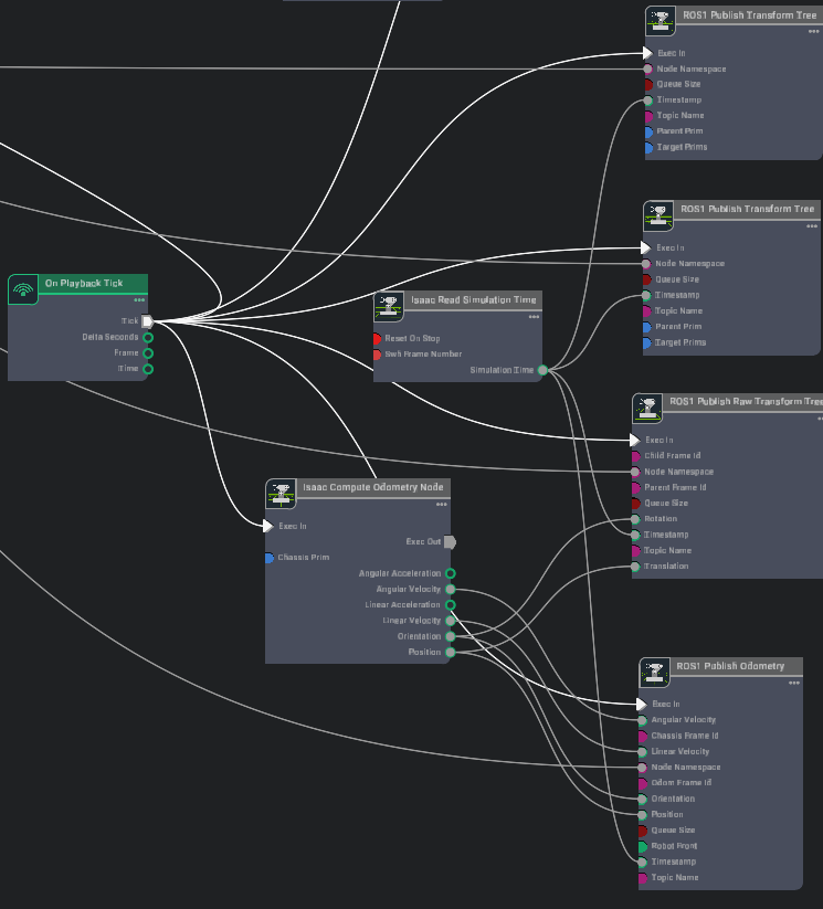
下列 ROS Omnigraph 節點負責驅動機器人導航:
Omnigraph 節點 功能說明 ros1_subscribe_twist訂閱 /cmd_vel話題,將接收到的速度指令傳給差速與關節控制器,控制機器人運動。isaac compute odometry node 它接收來自仿真環境或底層傳感器(如 IMU、輪編碼器)的原始運動數據,執行必要的計算(如積分、濾波、運動學解算),輸出機器人當前的狀態估計。 ros1_publish_odometry接收來自 Compute Odometry Node的完整狀態信息(位置、姿態、線速度、角速度),將其封裝成標準的 ROSnav_msgs/Odometry消息,并發布到指定的 ROS topic 上。ros1_publish_raw_transform_tree接收來自 Compute Odometry Node的位置和姿態信息,將其轉換為 ROS 的坐標變換 (tf transform),并按照指定的父子坐標系關系持續發布到 ROStf樹中。ros1_publish_transform_tree發布機器人基座坐標系(base_link)到底盤坐標系(chassis_link)的靜態變換;由于目標 prim 設置為 Carter_ROS,會把整個 Carter 機器人從chassis_link開始的層級樹都作為base_link的子樹一起發布。ros1_publish_transform_tree_01發布底盤坐標系(chassis_link)到激光雷達坐標系(carter_lidar)的靜態變換。 ros1_publish_laser_scan發布由 isaac_read_lidar_beams_node讀取的 2D 激光掃描(LaserScan)數據。 -
同樣在 Carter_ROS 下,右鍵點擊 ROS_Cameras,選擇 Open Graph。下列 ROS 相機相關 Omnigraph 節點負責圖像與相機信息的發布:
這個好理解,就是有兩個相機,然后每個相機都要進行渲染畫面,然后分成三種類型和話題發布。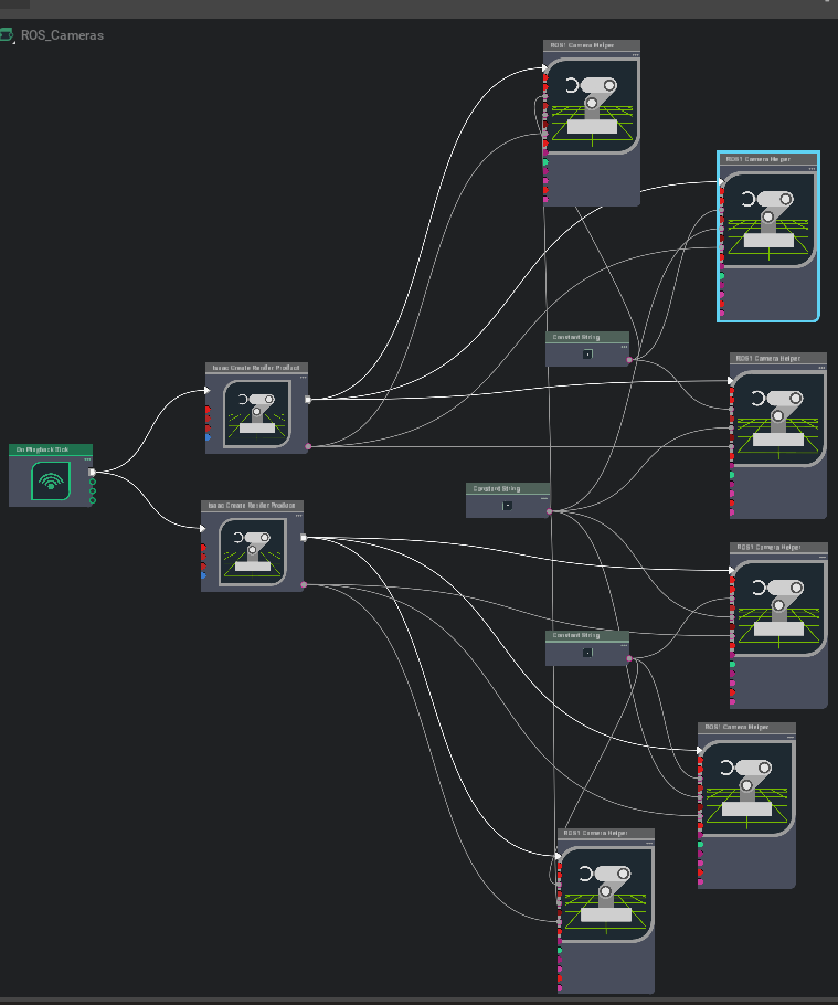
Omnigraph 節點 功能說明 ros1_create_camera_left_info自動生成并發布 /camera_info_left的CameraInfo,默認已啟用enable_camera_left分支節點。ros1_create_camera_left_rgb自動生成并發布 /rgb_left的 RGB 圖像,默認已啟用enable_camera_left和enable_camera_left_rgb。ros1_create_camera_left_depth自動生成并發布 /depth_left的深度圖(32FC1),需啟用enable_camera_left和enable_camera_left_depth。ros1_create_camera_right_info自動生成并發布 /camera_info_right的CameraInfo,需啟用enable_camera_right。ros1_create_camera_right_rgb自動生成并發布 /rgb_right的 RGB 圖像,默認已啟用enable_camera_right和enable_camera_right_rgb。ros1_create_camera_right_depth自動生成并發布 /depth_right的深度圖(32FC1),需啟用enable_camera_right和enable_camera_right_depth。 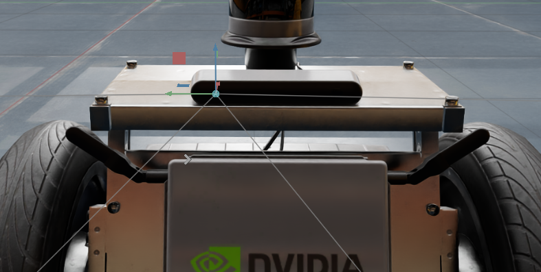
- 為了讓所有外部 ROS 節點使用仿真時間,還額外添加了一個 ROS_Clock Graph,包含一個
ros1_publish_clock節點,負責將仿真時間發布到/clock話題。
2.4 生成 Occupancy Map
使用占據地圖生成器擴展(推薦)
要了解更多關于占據地圖生成器擴展的信息,請點擊此處。
-
在 Isaac Examples → ROS → Navigation 中加載倉庫場景(warehouse scenario)。
-
在視口左上角,點擊 Camera,從下拉菜單中選擇 Top(俯視圖)。
-
進入 Isaac Utils → Occupancy Map。
-
在 Occupancy Map 擴展面板中:
-
將 Origin 設置為
X: 0.0, Y: 0.0, Z: 0.0。 -
將 Lower Bound 的
Z設置為0.1。 -
將 Upper Bound 的
Z設置為0.62。
提示:將上界
Z設為 0.62 米,是為了與 Carter 機器人上激光雷達距離地面的垂直高度保持一致。 -
-
在場景(Stage)中選中
warehouse_with_forklifts這個 prim。 -
返回 Occupancy Map 擴展面板,點擊 BOUND SELECTION。此時,占據地圖的邊界將根據所選
warehouse_with_forkliftsprim 自動更新。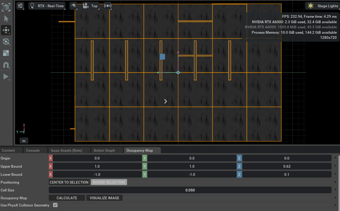
此時,面板中的地圖參數就會類似于下圖所示。
移除 Carter_ROS prim 并生成導航地圖
-
移除 Carter_ROS prim
在場景(Stage)中,選中Carter_ROSprim,按 Delete 鍵將其移除。 -
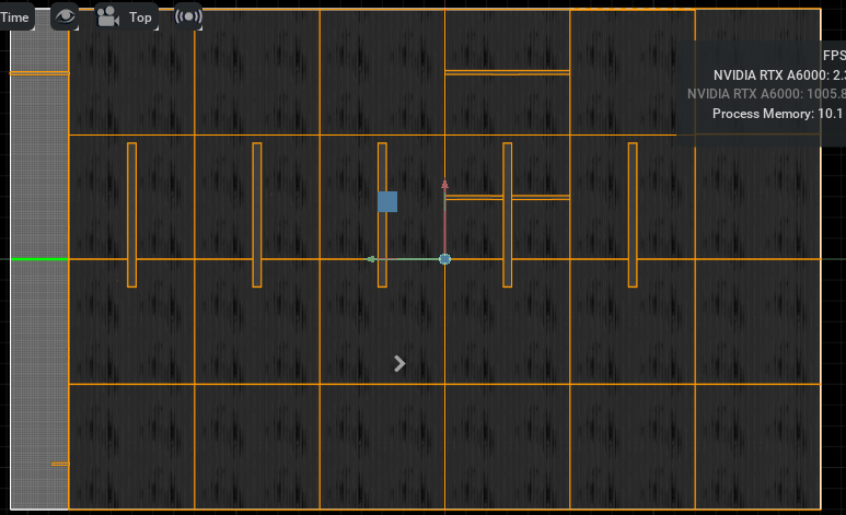
計算并可視化占據圖像
-
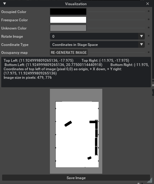
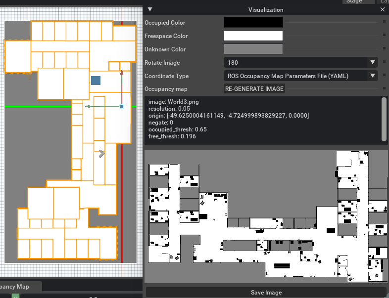
在 Occupancy Map 擴展面板中,依次點擊 CALCULATE,然后點擊 VISUALIZE IMAGE。
-
彈出可視化窗口后,設置:
-
Rotate Image:選擇 180 degrees。
-
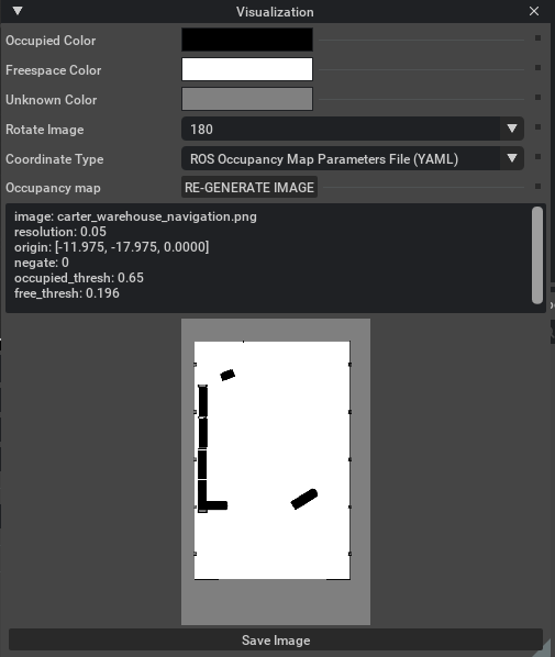
Coordinate Type:選擇 ROS Occupancy Map Parameters File (YAML)。
-
-
點擊 RE-GENERATE IMAGE,重新生成圖像(因為 ROS 相機與 Isaac Sim 相機坐標系不同,需要翻轉)。
-
-
導出 YAML 參數
-
在可視化面板下方,即刻會顯示一段符合 ROS 格式的 Occupancy Map 參數(YAML 文本)。
-
復制全部文本內容。
image: carter_warehouse_navigation.png
resolution: 0.05
origin: [-11.975, -17.975, 0.0000]
negate: 0
occupied_thresh: 0.65
free_thresh: 0.196
-
-
創建并保存 YAML 文件
在你的carter_2dnavROS 包的map目錄下(路徑示例:<noetic_ws>/src/navigation/carter_2dnav/map/),新建一個名為carter_warehouse_navigation.yaml 的文件,將剪貼板中復制的 YAML 文本粘貼到該文件中并保存。 -
保存可視化圖像:
回到 Omniverse Isaac Sim 可視化窗口,點擊 Save Image。將文件命名為?carter_warehouse_navigation.png,將它保存在與carter_warehouse_navigation.yaml相同的目錄中。
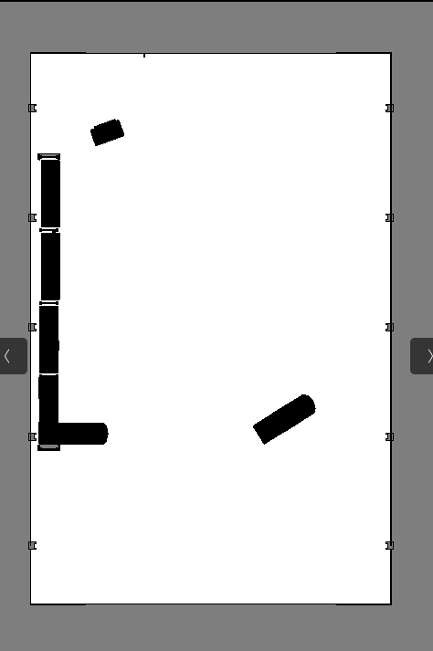 An occupancy map 現在就準備好了
2.5 運行 ROS Navigation
-
在 Isaac Examples → ROS → Navigation 中加載倉庫場景(warehouse scenario)。
-
點擊 Play 按鈕,啟動仿真。
-
打開一個新終端,運行以下 ROS 啟動文件,開啟導航流程:
這時 RViz 會自動打開,加載機器人的 URDF 模型、全局占據地圖,以及覆蓋其上的局部代價地圖。roslaunch carter_2dnav carter_navigation.launch 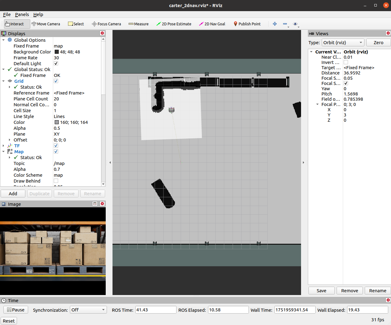
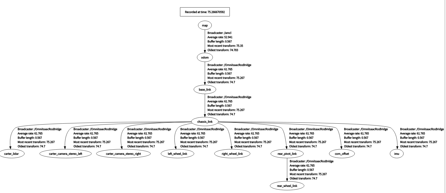
- 為驗證所有坐標變換(TF)都正常廣播,再打開一個新終端,運行:
rosrun rqt_tf_tree rqt_tf_tree彈出的 TF 樹圖應與下圖大致相符。
-
由于
carter_navigation.launch中已定義機器人的初始位姿,啟動時機器人會自動定位好;如有需要,也可在 RViz 中點擊 2D Pose Estimate 按鈕,手動重置位姿。 -
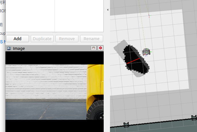
在 RViz 中,點擊工具欄上的 2D Nav Goal,然后在地圖上點擊并拖拽至目標點。
ROS Navigation 棧會立即規劃一條軌跡,機器人也會像開了自動駕駛模式一樣,朝著目的地優雅行駛!
可以看到拖拽到損失很大的障礙物處是沒法繼續移動的。
3. 多機器人ROS導航
3.1 建map
-
Create -> Isaac -> Environments -> Hospital.
-
Perspective--Top. 選中 Hospital prim and press F
-
Next, go to Isaac Utils -> Occupancy Map.
-
In the Occupancy Map extension, ensure the Origin is set to
X: 0.0, Y: 0.0, Z: 0.0. For the lower bound, setZ: 0.1. For the Upper Bound, setZ: 0.62. Keep in mind, the upper bound Z distance has been set to 0.62 meters to match the vertical distance of the Lidar onboard Carter with respect to the ground. -
Select the Hospital prim in the stage. In the Occupancy Map extension, click on
BOUND SELECTION. The bounds of the occupancy map should be updated to incorporate the selected Hospital prim. -
?
CALCULATEfollowed byVISUALIZE IMAGE. -
For Rotate Image, select 180 degrees and for Coordinate Type select
ROS Occupancy Map Parameters File (YAML). ClickRE-GENERATE IMAGE. Occupancy map parameters formatted to YAML will appear in the field below. Change the image name to your preference. Copy the full text. -
Create a YAML file for the occupancy map parameters called
carter_hospital_navigation.yamland place it in the map directory which is located in the samplecarter_2dnavROS package (carter_2dnav/map/carter_hospital_navigation.yaml). -
Insert the previously copied text in the
carter_hospital_navigation.yamlfile.
3.2 開始運行
-
Load scenario:
-
For the hospital environment, go to Isaac Examples -> ROS -> Multi Robot Navigation -> Hospital Scene.
-
For the Office scenario, go to Isaac Examples -> ROS -> Multi Robot Navigation -> Office Scene.
-
-
Click on
Playto begin simulation. -
In a new terminal, run the ROS launch file and set the env_name parameter to either hospital or office to begin Multiple Robot Navigation with the desired environment.
roslaunch carter_2dnav multiple_robot_carter_navigation.launch env_name:=hospital
To verify that all of the transforms are broadcasting, run the following command in a new terminal to visualize the ROS TF frame tree:
rosrun rqt_tf_tree rqt_tf_treeSince the positions of each robot is defined in multiple_robot_carter_navigation.launch, the robots should already be properly localized.
-
In RViz, 點擊 Tool Properties -> 2D Nav Goal -> Topic, 設置 topic namespace to either
/carter1,/carter2or/carter3選擇給哪一個導航 -
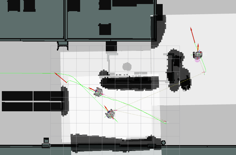
Next, click on the
2D Nav Goalbutton and then click and drag at the desired location point in the map. The ROS Navigation stack will now generate a trajectory and the specified robot will start moving towards its destination! Repeat this process for every other robot.


)


)


)

)


)
