學習內容
需求
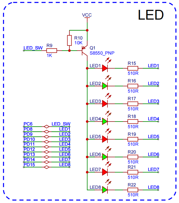
點亮4個燈,采用pwm的方式。
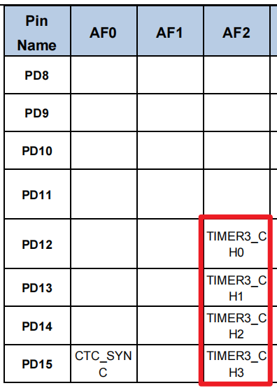
定時器 | 通道 | 引腳 | AF | LED序號 |
T3 | CH0 | PD12 | AF2 | LED5 |
CH1 | PD13 | AF2 | LED6 | |
CH2 | PD14 | AF2 | LED7 | |
CH3 | PD15 | AF2 | LED8 |
實現LED5, LED6, LED7, LED8呼吸燈效果
通用定時器多通道
點亮T3定時器下的多個通道的燈。
開發流程
- 添加Timer依賴
- 初始化PWM相關GPIO
- 初始化PWM,包含多通道配置
- PWM占空比控制
多通道配置
void timer_channel_config(uint32_t timer_periph, uint16_t channel) {/* TIMER 通道輸出配置 */timer_oc_parameter_struct ocpara;/* initialize TIMER channel output parameter struct */timer_channel_output_struct_para_init(&ocpara);/* 啟用P極輸出 */ocpara.outputstate  = (uint16_t)TIMER_CCX_ENABLE;/* 配置輸出參數 configure TIMER channel output function */timer_channel_output_config(timer_periph, channel, &ocpara);/* 配置通道輸出輸出比較模式 configure TIMER channel output compare mode */timer_channel_output_mode_config(timer_periph, channel, TIMER_OC_MODE_PWM0);
}
?
輸出比較模式
- TIMER_OC_MODE_PWM0: 高電平有效
- TIMER_OC_MODE_PWM1:低電平有效
占空比更新
/*********************************************************** @brief 更新pwm占空比* @param timer_periph 定時器* @param channel 通道* @param duty  占空比[0, 100]* @return **********************************************************/
void PWM_update(uint32_t timer_periph, uint16_t channel, float duty) { // 0-100if(duty > 100) duty = 100;else if(duty < 0) duty = 0;//	pulse / PERIOD == duty / 100uint32_t pulse = PERIOD * duty / 100.0f - 1;// 計數值 65535timer_channel_output_pulse_value_config(timer_periph, channel, pulse);
}
?完整代碼
#include "gd32f4xx.h"
#include "systick.h"
#include <stdio.h>
#include "main.h"
#include "USART0.h"void USART0_on_recv(uint8_t* data, uint32_t len) {printf("g_rx_buffer: %s g_rx_cnt:%d \n", data, len);
}static void GPIO_config() {rcu_periph_clock_enable(RCU_GPIOC);gpio_mode_set(GPIOC, GPIO_MODE_OUTPUT, GPIO_PUPD_NONE, GPIO_PIN_6);gpio_output_options_set(GPIOC, GPIO_OTYPE_PP, GPIO_OSPEED_50MHZ, GPIO_PIN_6);gpio_bit_reset(GPIOC, GPIO_PIN_6);
}void timer_gpio_config(uint32_t gpio_rcu, uint32_t gpio_port, uint32_t gpio_pin, uint32_t gpio_af) {rcu_periph_clock_enable(gpio_rcu);/* 設置gpio模式 */gpio_mode_set(gpio_port, GPIO_MODE_AF, GPIO_PUPD_NONE, gpio_pin);gpio_output_options_set(gpio_port, GPIO_OTYPE_PP, GPIO_OSPEED_MAX, gpio_pin);gpio_af_set(gpio_port, gpio_af, gpio_pin);
}void timer_init_config(rcu_periph_enum rcu_periph, uint32_t timer_periph,uint16_t t_prescaler, uint32_t t_period) {rcu_periph_clock_enable(rcu_periph);timer_deinit(timer_periph);/*初始化參數 */timer_parameter_struct initpara;/* initialize TIMER init parameter struct */timer_struct_para_init(&initpara);/* 根據需要配置值 分頻系數 (可以實現更低的timer頻率) */initpara.prescaler 	= t_prescaler - 1;/* 1個周期的計數(period Max: 65535) Freq > 3662  */initpara.period		= t_period - 1;/* initialize TIMER counter */timer_init(timer_periph, &initpara);/* enable a TIMER */timer_enable(timer_periph);}void timer_channel_config(uint32_t timer_periph, uint16_t channel) {/* TIMER 通道輸出配置 */timer_oc_parameter_struct ocpara;/* initialize TIMER channel output parameter struct */timer_channel_output_struct_para_init(&ocpara);ocpara.outputstate  = (uint16_t)TIMER_CCX_ENABLE;/* 配置輸出參數 configure TIMER channel output function */timer_channel_output_config(timer_periph, channel, &ocpara);/* 配置通道輸出輸出比較模式 configure TIMER channel output compare mode */timer_channel_output_mode_config(timer_periph, channel, TIMER_OC_MODE_PWM0);
}// TIMER CH
#define LED5 TIMER3, TIMER_CH_0
#define LED6 TIMER3, TIMER_CH_1
#define LED7 TIMER3, TIMER_CH_2
#define LED8 TIMER3, TIMER_CH_3// PWM
#define	PRESCALER		1
#define	FREQ			  10000
#define PERIOD			(SystemCoreClock / FREQ)// LED5 TM3CH0 PD12
// LED6 TM3CH1 PD13
// LED7 TM3CH2 PD14
// LED8 TM3CH3 PD15
static void Timer_config() {// 定時器// GPIO ----------------------------------------timer_gpio_config(RCU_GPIOD, GPIOD, GPIO_PIN_12, GPIO_AF_2);timer_gpio_config(RCU_GPIOD, GPIOD, GPIO_PIN_13, GPIO_AF_2);timer_gpio_config(RCU_GPIOD, GPIOD, GPIO_PIN_14, GPIO_AF_2);timer_gpio_config(RCU_GPIOD, GPIOD, GPIO_PIN_15, GPIO_AF_2);// TIMER----------------------------------------/* 升級頻率*/rcu_timer_clock_prescaler_config(RCU_TIMER_PSC_MUL4);timer_init_config(RCU_TIMER3, TIMER3, PRESCALER, PERIOD); // 與通道無關// TIMER channel-------------------------------timer_channel_config(LED5);timer_channel_config(LED6);timer_channel_config(LED7);timer_channel_config(LED8);}/*********************************************************** @brief 更新pwm占空比* @param timer_periph 定時器* @param channel 通道* @param duty  占空比[0, 100]* @return **********************************************************/
void PWM_update(uint32_t timer_periph, uint16_t channel, float duty) { // 0-100if(duty > 100) duty = 100;else if(duty < 0) duty = 0;//	pulse / PERIOD == duty / 100uint32_t pulse = PERIOD * duty / 100.0f - 1;// 計數值 65535timer_channel_output_pulse_value_config(timer_periph, channel, pulse);
}int main(void)
{systick_config();USART0_init();// 拉低總開關
//  GPIO_config();Timer_config();printf("Init Complete!\n");float duty = 0;int8_t dir = 1;while(1) {PWM_update(LED5, duty);PWM_update(LED6, duty);PWM_update(LED7, duty);PWM_update(LED8, duty);if (duty >= 100) {dir = -1;} else if (duty <= 0) {dir = 1;}duty += dir;printf("duty: %.2f \n", duty);delay_1ms(10);}
}
高級定時器通道輸出
高級定時器只有TIMER0和TIMER7支持。由于擴展板上的高級定時器沒有對應的LED,我們可以使用跳線的方式,將TIMER0CH0對應的PE8引腳,短接到PD8(LED1)上,通過觀察LED1的亮滅,了解是否正確輸出。
開發流程
- 添加Timer依賴
- 初始化PWM,包含多通道配置
- Break配置
- PWM占空比控制
通道配置
void timer0_channel_config(uint32_t timer_periph, uint16_t channel) {/* TIMER 通道輸出配置 */timer_oc_parameter_struct ocpara;/* initialize TIMER channel output parameter struct */timer_channel_output_struct_para_init(&ocpara);// 禁用 OP極
//  ocpara.outputstate  = TIMER_CCX_ENABLE;// 啟用 ON極ocpara.outputnstate = TIMER_CCXN_ENABLE;/* 配置輸出參數 configure TIMER channel output function */timer_channel_output_config(timer_periph, channel, &ocpara);/* 配置通道輸出輸出比較模式 configure TIMER channel output compare mode */timer_channel_output_mode_config(timer_periph, channel, TIMER_OC_MODE_PWM0);
}#define LED1 TIMER0, TIMER_CH_0timer0_channel_config(LED1);- 特別強調,這里的引腳分為P和N類型,不同引腳要配置不同的輸出狀態
Break配置
// break 只針對高級定時器TIMER0 & TIMER7,需要打開互補保護電路/* TIMER通道互補保護電路 */
timer_break_parameter_struct breakpara;
/* 初始化TIMER break參數結構體 */
timer_break_struct_para_init(&breakpara);
/* break輸入的極性 HIGH */
breakpara.breakpolarity   = TIMER_BREAK_POLARITY_HIGH;
/* 輸出自動的啟用 */
breakpara.outputautostate = TIMER_OUTAUTO_ENABLE;
/* bread輸入的啟用*/
breakpara.breakstate     = TIMER_BREAK_ENABLE;
/* 配置TIMER7 break */
timer_break_config(TIMER0, &breakpara);
/* 啟用TIMER7 break */
timer_break_enable(TIMER0);- breakstate:break狀態開啟
- ouputostate:輸出狀態,自動開啟
- breakpolarity:輸出極性,高電平
在ARM32中的高級定時器配置中,break參數用于增強安全性和控制功能,特別是在電機控制或功率轉換應用中,避免因故障導致不必要的輸出操作。
每個參數的作用和意義:
- runoffstate(溢出狀態的運行)
參數示例:TIMER_ROS_STATE_DISABLE
作用:當定時器運行狀態切換到溢出狀態時,是否自動關閉輸出信號。DISABLE表示不進行自動關閉。 - ideloffstate(空閑狀態的關閉)
參數示例:TIMER_IOS_STATE_DISABLE
作用:當定時器進入空閑狀態時,是否自動關閉輸出信號。DISABLE表示不進行關閉。 - deadtime(死區時間)
參數示例:255
作用:定義死區時間(Dead Time),主要用于避免在切換高低驅動時,兩個輸出的驅動器同時導通,導致短路或過流。255表示配置了較大的死區時間。 - breakpolarity(斷路信號極性)
參數示例:TIMER_BREAK_POLARITY_LOW
作用:定義break信號的極性。在此配置中,當斷路信號為低電平時觸發break事件,停止輸出。 - outputautostate(自動輸出狀態)
參數示例:TIMER_OUTAUTO_ENABLE
作用:使能或禁用在break事件后自動恢復輸出。當ENABLE時,break事件處理完成后,定時器輸出可以自動恢復。 - protectmode(保護模式)
參數示例:TIMER_CCHP_PROT_0
作用:保護模式用于設置對輸出寄存器的保護級別,防止在某些狀態下被誤修改。TIMER_CCHP_PROT_0表示最低保護級別,允許對輸出進行修改。 - breakstate(斷路狀態)
參數示例:TIMER_BREAK_ENABLE
作用:開啟或禁用break功能。ENABLE表示當檢測到斷路信號時,會停止輸出以保護系統。
這些參數主要用于配置定時器的安全控制,break功能在高電壓或高功率應用中非常關鍵。當發生異常或檢測到故障(比如過流或短路)時,可以通過break功能立即停止PWM等輸出信號,避免硬件損壞。
互補保護電路:用于驅動H橋或三相逆變器,當檢測到故障(如短路)時,通過外部硬件信號(Break)快速關閉PWM輸出,避免損壞MOSFET/IGBT。
高級定時器:支持死區時間、互補輸出等復雜功能,常用于電機控制、電源轉換等場景。
完整代碼
#include "gd32f4xx.h"
#include "systick.h"
#include <stdio.h>
#include "main.h"
#include "USART0.h"void USART0_on_recv(uint8_t* data, uint32_t len) {printf("g_rx_buffer: %s g_rx_cnt:%d \n", data, len);
}static void GPIO_config() {rcu_periph_clock_enable(RCU_GPIOC);gpio_mode_set(GPIOC, GPIO_MODE_OUTPUT, GPIO_PUPD_NONE, GPIO_PIN_6);gpio_output_options_set(GPIOC, GPIO_OTYPE_PP, GPIO_OSPEED_50MHZ, GPIO_PIN_6);gpio_bit_reset(GPIOC, GPIO_PIN_6);
}void timer_gpio_config(uint32_t gpio_rcu, uint32_t gpio_port, uint32_t gpio_pin, uint32_t gpio_af) {rcu_periph_clock_enable(gpio_rcu);/* 設置gpio模式 */gpio_mode_set(gpio_port, GPIO_MODE_AF, GPIO_PUPD_NONE, gpio_pin);gpio_output_options_set(gpio_port, GPIO_OTYPE_PP, GPIO_OSPEED_MAX, gpio_pin);gpio_af_set(gpio_port, gpio_af, gpio_pin);
}void timer_init_config(rcu_periph_enum rcu_periph, uint32_t timer_periph,uint16_t t_prescaler, uint32_t t_period) {rcu_periph_clock_enable(rcu_periph);timer_deinit(timer_periph);/*初始化參數 */timer_parameter_struct initpara;/* initialize TIMER init parameter struct */timer_struct_para_init(&initpara);/* 根據需要配置值 分頻系數 (可以實現更低的timer頻率) */initpara.prescaler 	= t_prescaler - 1;/* 1個周期的計數(period Max: 65535) Freq > 3662  */initpara.period		= t_period - 1;/* initialize TIMER counter */timer_init(timer_periph, &initpara);/* enable a TIMER */timer_enable(timer_periph);}void timer0_channel_config(uint32_t timer_periph, uint16_t channel) {/* TIMER 通道輸出配置 */timer_oc_parameter_struct ocpara;/* initialize TIMER channel output parameter struct */timer_channel_output_struct_para_init(&ocpara);// 禁用 OP極
//  ocpara.outputstate  = TIMER_CCX_ENABLE;// 啟用用 OP極ocpara.outputnstate = TIMER_CCXN_ENABLE;/* 配置輸出參數 configure TIMER channel output function */timer_channel_output_config(timer_periph, channel, &ocpara);/* 配置通道輸出輸出比較模式 configure TIMER channel output compare mode */timer_channel_output_mode_config(timer_periph, channel, TIMER_OC_MODE_PWM0);
}// TIMER CH
#define LED1 TIMER0, TIMER_CH_0// PWM
#define	PRESCALER		1
#define	FREQ			  10000
#define PERIOD			(SystemCoreClock / FREQ)// LED1 TM0CH0_ON PE8
static void Timer_config() {// 定時器// GPIO ----------------------------------------timer_gpio_config(RCU_GPIOE, GPIOE, GPIO_PIN_8,  GPIO_AF_1);// TIMER----------------------------------------/* 升級頻率*/rcu_timer_clock_prescaler_config(RCU_TIMER_PSC_MUL4);timer_init_config(RCU_TIMER0, TIMER0, PRESCALER, PERIOD); // 與通道無關// TIMER channel-------------------------------timer0_channel_config(LED1);// Break --------------------------------------------------// break 只針對高級定時器TIMER0 & TIMER7,打開互補保護電路/* TIMER通道互補保護電路 */timer_break_parameter_struct breakpara;/* 初始化TIMER break參數結構體 */timer_break_struct_para_init(&breakpara);/* break輸入的極性 HIGH */breakpara.breakpolarity   = TIMER_BREAK_POLARITY_HIGH;/* 輸出自動的啟用 */breakpara.outputautostate = TIMER_OUTAUTO_ENABLE;/* bread輸入的啟用*/breakpara.breakstate     = TIMER_BREAK_ENABLE;/* 配置TIMER7 break */timer_break_config(TIMER0, &breakpara);/* 啟用TIMER7 break */timer_break_enable(TIMER0);
}/*********************************************************** @brief 更新pwm占空比* @param timer_periph 定時器* @param channel 通道* @param duty  占空比[0, 100]* @return**********************************************************/
void PWM_update(uint32_t timer_periph, uint16_t channel, float duty) { // 0-100if(duty > 100) duty = 100;else if(duty < 0) duty = 0;//	pulse / PERIOD == duty / 100uint32_t pulse = PERIOD * duty / 100.0f - 1;// 計數值 65535timer_channel_output_pulse_value_config(timer_periph, channel, pulse);
}int main(void)
{systick_config();USART0_init();// 拉低總開關GPIO_config();Timer_config();printf("Init Complete!\n");float duty = 0;int8_t dir = 1;while(1) {PWM_update(LED1, duty);if (duty >= 100) {dir = -1;} else if (duty <= 0) {dir = 1;}duty += dir;printf("duty: %.2f \n", duty);delay_1ms(10);}
}
day15)


)


![[CH582M入門第十一步]DS18B20驅動](http://pic.xiahunao.cn/[CH582M入門第十一步]DS18B20驅動)


