一、實驗目的
-
完成網絡設備(路由器 R1-R5、PC1-PC4)的 IP 地址規劃與配置,確保接口通信基礎正常。
-
配置鏈路層協議及認證:R1 與 R5 采用 PPP 的 PAP 認證(R5 為主認證方),R2 與 R5 采用 PPP 的 CHAP 認證(R5 為主認證方),R3 與 R5 采用 HDLC 封裝。
-
實現隧道配置:R1、R2、R3 構建 MGRE 環境(R1 為中心站點),R1 與 R4 構建點到點 GRE 隧道。
-
配置 RIP 路由協議,實現私有網絡全網可達。
-
配置 NAT(Easy IP),使所有 PC 以私有 IP 為源 IP 訪問 R5 的環回接口(5.5.5.5/24)。
二、實驗環境
-
設備:路由器 R1、R2、R3、R4、R5(R5 作為 ISP);PC1、PC2、PC3、PC4。
-
接口類型:GigabitEthernet(GE,千兆以太網接口)、Serial(串行接口,用于廣域網連接)、LoopBack(環回接口)。
-
協議:PPP(PAP/CHAP 認證)、HDLC、GRE、MGRE、RIP v2、NAT。
三、實驗拓撲與地址規劃
1. 拓撲圖
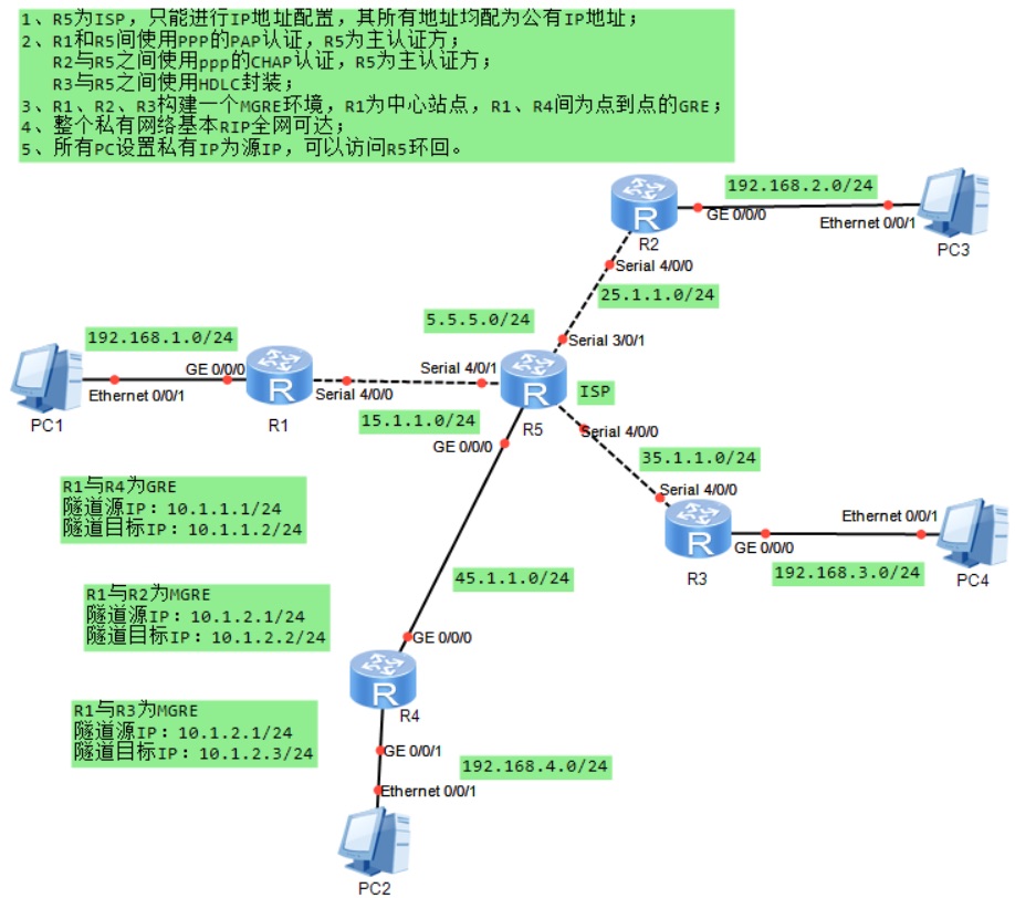
2. 地址規劃表
| 設備 | 接口 | IP 地址 / 子網掩碼 | 對應網段 |
|---|---|---|---|
| R1 | GE0/0/0 | 192.168.1.254/24 | 192.168.1.0/24(私有) |
| R1 | Serial4/0/0 | 15.1.1.1/24 | 15.1.1.0/24(公有) |
| R1 | Tunnel0/0/0(GRE) | 10.1.1.1/24 | 10.1.1.0/24(隧道私有) |
| R1 | Tunnel0/0/1(MGRE) | 10.1.2.1/24 | 10.1.2.0/24(隧道私有) |
| R2 | GE0/0/0 | 192.168.2.254/24 | 192.168.2.0/24(私有) |
| R2 | Serial4/0/0 | 25.1.1.2/24 | 25.1.1.0/24(公有) |
| R2 | Tunnel0/0/1(MGRE) | 10.1.2.2/24 | 10.1.2.0/24(隧道私有) |
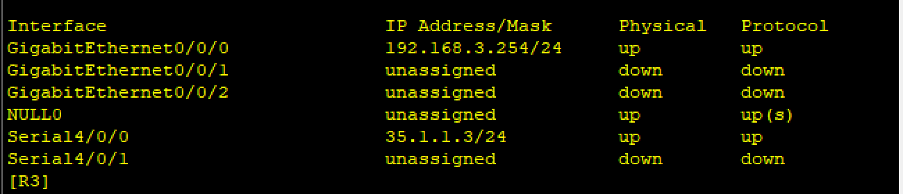
| R3 | GE0/0/0 | 192.168.3.254/24 | 192.168.3.0/24(私有) |
| R3 | Serial4/0/0 | 35.1.1.3/24 | 35.1.1.0/24(公有) |
| R3 | Tunnel0/0/1(MGRE) | 10.1.2.3/24 | 10.1.2.0/24(隧道私有) |
| R4 | GE0/0/0 | 192.168.4.254/24 | 192.168.4.0/24(私有) |
| R4 | GE0/0/1 | 45.1.1.4/24 | 45.1.1.0/24(公有) |
| R4 | Tunnel0/0/0(GRE) | 10.1.1.4/24 | 10.1.1.0/24(隧道私有) |
| R5(ISP) | LoopBack0 | 5.5.5.5/24 | 5.5.5.0/24(公有) |
| R5 | Serial4/0/1 | 15.1.1.5/24 | 15.1.1.0/24(公有) |
| R5 | Serial3/0/1 | 25.1.1.5/24 | 25.1.1.0/24(公有) |
| R5 | Serial4/0/0 | 35.1.1.5/24 | 35.1.1.0/24(公有) |
| R5 | GE0/0/0 | 45.1.1.5/24 | 45.1.1.0/24(公有) |
| PC1 | Ethernet0/0/1 | 192.168.1.1/24 | 192.168.1.0/24(私有) |
| PC2 | Ethernet0/0/1 | 192.168.4.2/24 | 192.168.4.0/24(私有) |
| PC3 | Ethernet0/0/1 | 192.168.2.3/24 | 192.168.2.0/24(私有) |
| PC4 | Ethernet0/0/1 | 192.168.3.4/24 | 192.168.3.0/24(私有) |
四、實驗步驟
第一步:IP 地址配置與靜態路由
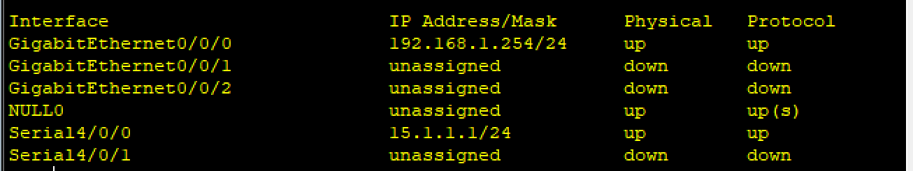
1. R1-R4 的 IP 配置
以 R1 為例,其余設備配置邏輯相同:
[R1]int g 0/0/0
[R1-GigabitEthernet0/0/0]ip add 192.168.1.254 24
[R1-GigabitEthernet0/0/0]int s 4/0/0
[R1-Serial4/0/0]ip add 15.1.1.1 24
R2-R4 關鍵配置:
-
R2:GE0/0/0(192.168.2.254/24)、Serial4/0/0(25.1.1.2/24)
-
R3:GE0/0/0(192.168.3.254/24)、Serial4/0/0(35.1.1.3/24)
-
R4:GE0/0/0(192.168.4.254/24)、GE0/0/1(45.1.1.4/24)
2.R5(ISP)的 IP 配置
[ISP]int l 0
[ISP-LoopBack0]ip add 5.5.5.5 24
[ISP-LoopBack0]q
[ISP]int s 4/0/1
[ISP-Serial4/0/1]ip add 15.1.1.5 24[ISP-Serial4/0/1]int s 3/0/1
[ISP-Serial3/0/1]ip add 25.1.1.5 24[ISP-Serial3/0/1]int s 4/0/0
[ISP-Serial4/0/0]ip add 35.1.1.5 24[ISP-Serial4/0/0]int g 0/0/0
[ISP-GigabitEthernet0/0/0]ip add 45.1.1.5 24
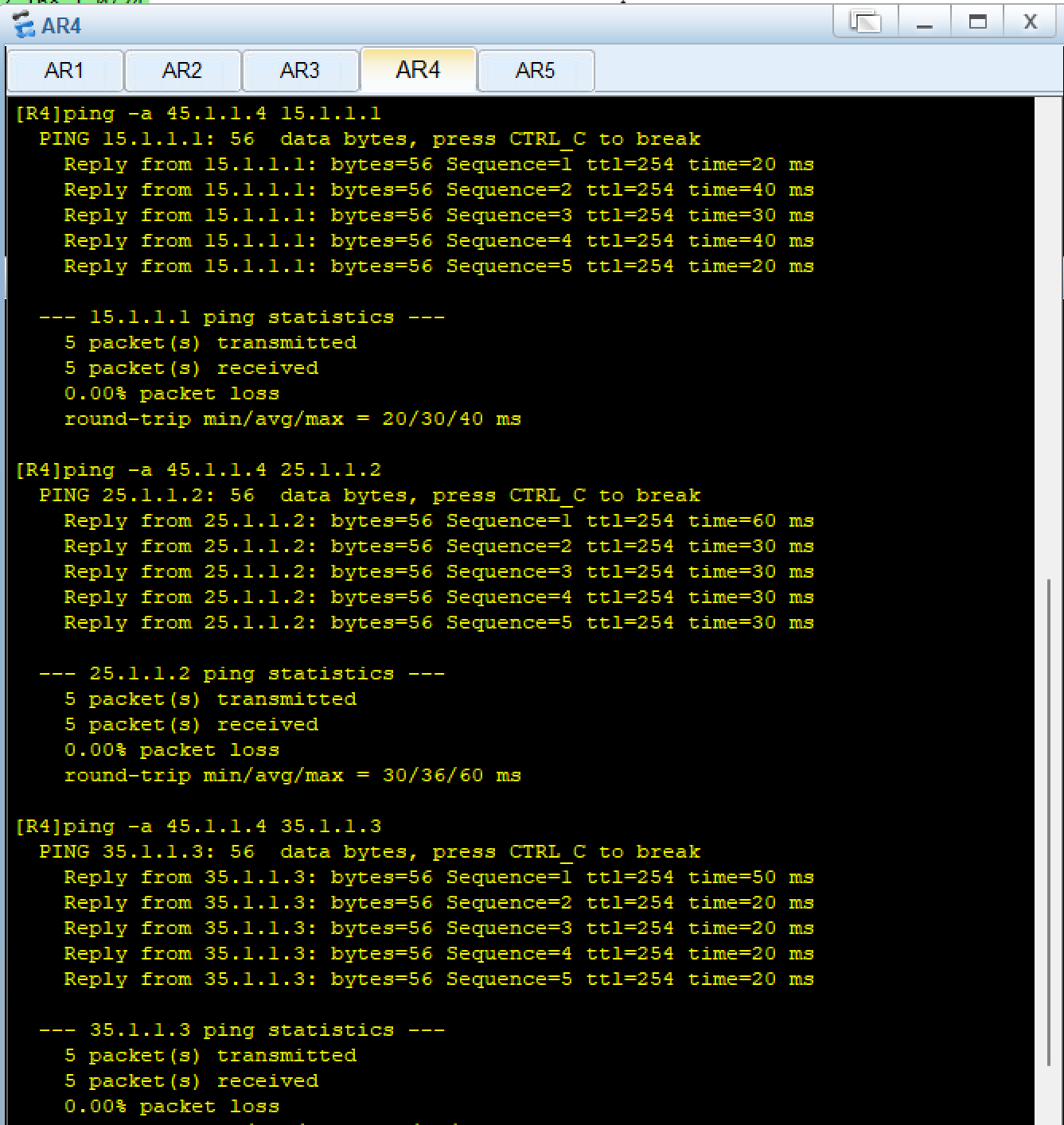
3. 靜態路由配置(默認路由)
目的:使私有網絡通過 R5 訪問公網(R5 環回)
[R1]IP route-static 0.0.0.0 0 15.1.1.5
[R2]IP route-static 0.0.0.0 0 25.1.1.5
[R3]IP route-static 0.0.0.0 0 35.1.1.5
[R4]IP route-static 0.0.0.0 0 45.1.1.5
第二步:鏈路層協議與認證配置
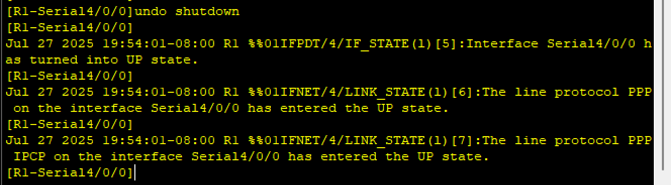
1. R1-R5(PAP 認證,R5 為主認證方)
[ISP]aaa
[ISP-aaa]local-user yu password cipher 12345 privilege level 15
Info: Add a new user.
[ISP-aaa]local-user yu service-type ppp
[ISP-aaa]q
[ISP]int s 4/0/1
[ISP-Serial4/0/1]link-protocol ppp
[ISP-Serial4/0/1]ppp authentication-mode pap[R1]int s 4/0/0
[R1-Serial4/0/0]link-protocol ppp
[R1-Serial4/0/0]ppp pap local-user yu password cipher 12345
- 驗證pap認證如下,或者用
dis ppp int s 4/0/0查看認證的狀態
2. R2-R5(CHAP 認證,R5 為主認證方)
R5用戶已在aaa 中創建,直接啟用 CHAP
[ISP]int s 3/0/1
[ISP-Serial3/0/1]ppp authentication-mode chap [R2]int s 4/0/0
[R2-Serial4/0/0]ppp chap user yu
[R2-Serial4/0/0]ppp chap password cipher 12345
- 驗證chap(同pap認證)
3. R3-R5(HDLC 封裝)
[ISP]int s 4/0/0
[ISP-Serial4/0/0]link-protocol hdlc [R3]int s 4/0/0
[R3-Serial4/0/0]link-protocol hdlc
- 驗證
第三步:隧道配置
1. R1-R4(點到點 GRE 隧道)
[R1]int t 0/0/0
[R1-Tunnel0/0/0]ip add 10.1.1.1 24
[R1-Tunnel0/0/0]tunnel-protocol gre
[R1-Tunnel0/0/0]source 15.1.1.1
[R1-Tunnel0/0/0]description 45.1.1.4[R4]int t 0/0/0
[R4-Tunnel0/0/0]ip add 10.1.1.4 24
[R4-Tunnel0/0/0]tunnel-protocol gre
[R4-Tunnel0/0/0]source 45.1.1.4
[R4-Tunnel0/0/0]description 15.1.1.1
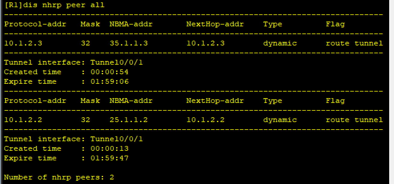
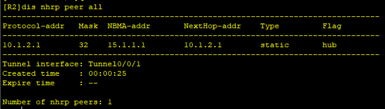
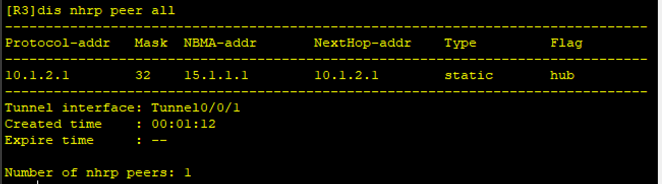
2. R1-R2-R3(MGRE 隧道,R1 為中心)
[R1]int Tunnel 0/0/1
[R1-Tunnel0/0/1]ip add 10.1.2.1 24
[R1-Tunnel0/0/1]tunnel-protocol gre p2mp
[R1-Tunnel0/0/1]source 15.1.1.1
[R1-Tunnel0/0/1]nhrp network-id 100
[R1-Tunnel0/0/1]nhrp entry multicast dynamic [R2]int Tunnel 0/0/1
[R2-Tunnel0/0/1]ip add 10.1.2.2 24
[R2-Tunnel0/0/1]tunnel-protocol gre p2mp
[R2-Tunnel0/0/1]source serial 4/0/0
[R2-Tunnel0/0/1]nhrp network-id 100
[R2-Tunnel0/0/1]nhrp entry 10.1.2.1 15.1.1.1 register [R3]int Tunnel 0/0/1
[R3-Tunnel0/0/1]ip add 10.1.2.3 24
[R3-Tunnel0/0/1]tunnel-protocol gre p2mp
[R3-Tunnel0/0/1]source serial 4/0/0
[R3-Tunnel0/0/1]nhrp network-id 100
[R3-Tunnel0/0/1]nhrp entry 10.1.2.1 15.1.1.1 register
第四步:RIP 路由配置(私有網絡全網可達)
1. 啟用 RIP v2 并宣告網絡
[R1]rip 1
[R1-rip-1]version 2
[R1-rip-1]undo summary
[R1-rip-1]network 192.168.1.0
[R1-rip-1]network 10.0.0.0 #A類地址,只關注前八位
R2、R3、R4步驟同理
- 驗證
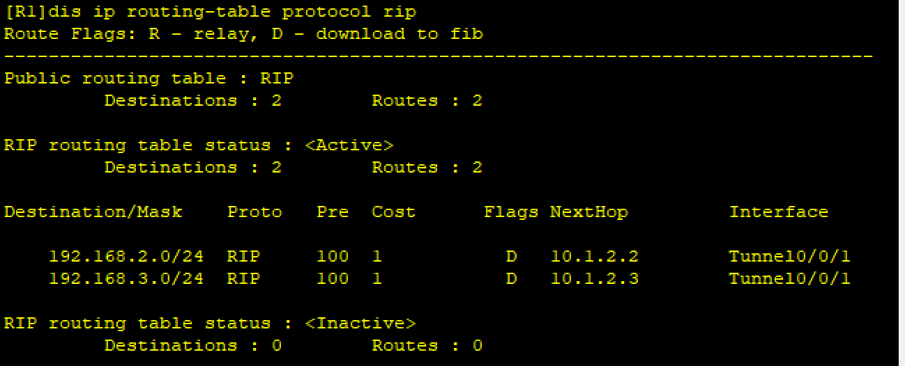
2. 關閉 MGRE 隧道水平分割
MGRE 為多點接口,水平分割會阻止路由轉發,需關閉:
[R1-Tunnel0/0/1]undo rip split-horizon
驗證:
第五步:NAT 配置(Easy IP)
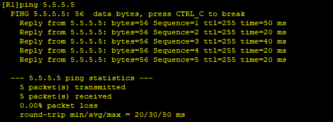
目的:將私有 IP 轉換為出口公網 IP,實現 PC 訪問 R5 環回(5.5.5.5)。
以 R1 為例,其余設備配置邏輯相同:
[R1]acl 2000
[R1-acl-basic-2000]rule permit source 192.168.1.0 0.0.0.255
[R1-acl-basic-2000]int s 4/0/0
[R1-Serial4/0/0]nat outbound 2000
R2、R3、R4同理
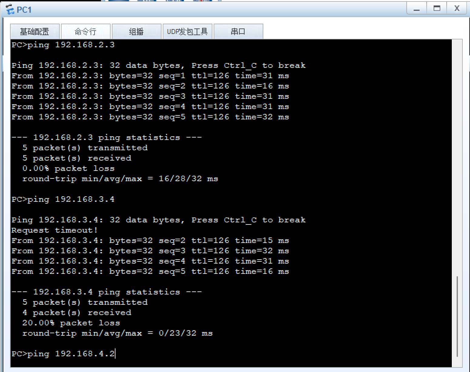
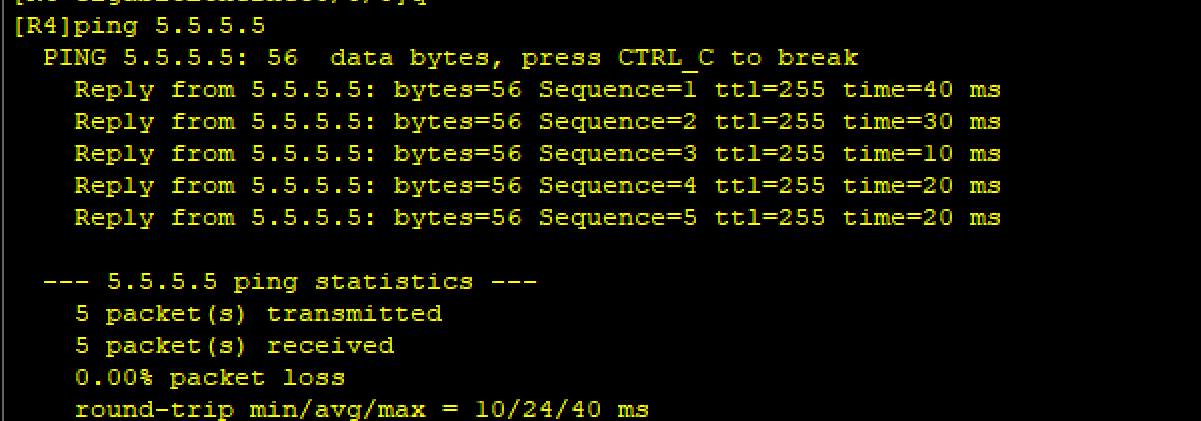
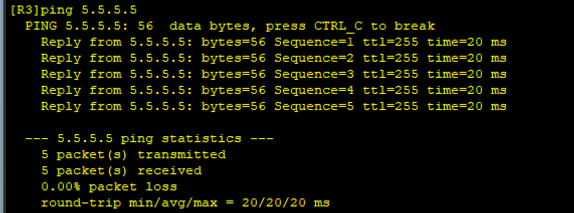
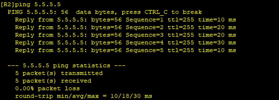
驗證:
五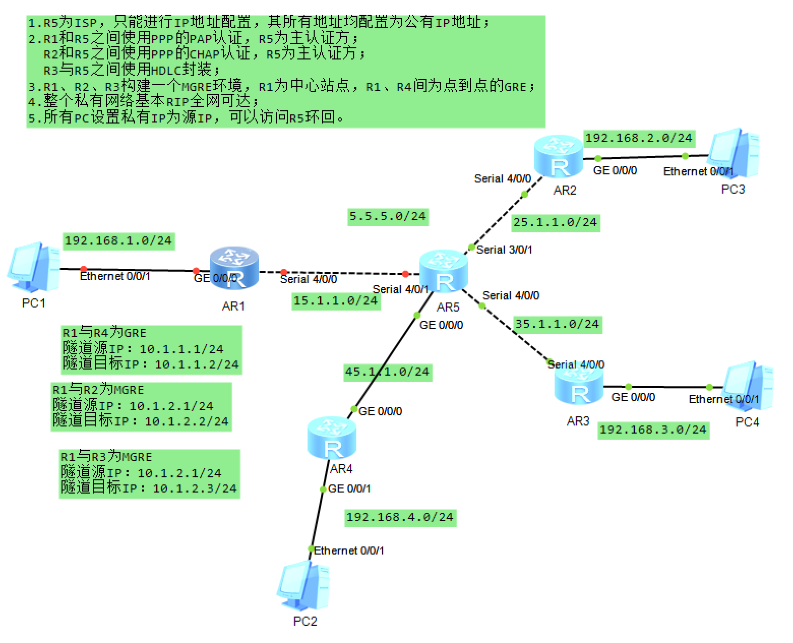
、實驗總結
本次實驗完成了網絡分層配置,包括 IP 規劃、鏈路層認證、隧道搭建、動態路由及 NAT 轉換,實現了私有網絡內部互通及訪問公網服務的目標。關鍵難點在于 MGRE 隧道的 NHRP 注冊和 RIP 水平分割的處理,通過逐步驗證每一步配置,確保了整體網絡的連通性。


的安裝過程以及GD32的IAR工程模板搭建)

 鑰匙串信息)
)

 配置IP封禁(防暴力破解))


——變量操作)
![[Linux入門] 初學者入門:Linux DNS 域名解析服務詳解](http://pic.xiahunao.cn/[Linux入門] 初學者入門:Linux DNS 域名解析服務詳解)
