1,目的。
- 測量3D翼片的距離與角度。
- 說明:
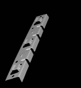
- 標注A 紅色框選的區域即為
翼片,本示例的3D 對象共有3個翼片待測。 L1與L2的距離、L1與L2的角度即為所求的翼片距離與角度。
- 標注A 紅色框選的區域即為


2,原理。
- 使用線結構光模型(標定模式)獲取作為參考對象的 3D 點云,以及結構光模型默認的
lightPlanepose,movementpose。 - 使用三個光平面與 作為參考對象的 3D 點云對象相交,獲取光平面與 3D 對象的交集點云,將該交集點云投影到2D 平面形成輪廓。
- 篩選出所需的輪廓
L1與L2,求出3組L1與L2的距離均值,角度均值,將該值作為標準值。 - 使用結構光模型獲取被測的 3D 點云,并將該3D點云與參考對象的3D點云進行表面匹配獲取Pose。
- 對三個光平面進行剛體變化,保證光平面與被測的3D點云相切,獲取切平面。
- 對被測對象的切平面進行投影,篩選出輪廓,計算輪廓的距離與角度是否在規定的范圍內。
3,程序解析。
3.1,創建參考 3D 對象樣本。
* 參考案例庫:inspect_3d_surface_intersections.hdev* 目的:測量三個金屬薄片翅凸起的角度與距離*
* ------------Part01,建立參考 3D 對象樣本* 1.1,配置線性結構光模型。
* 模式為‘calibration’,該模式將生成默認的lightpanelpose與movementpose,如果缺省則這兩個位姿為空
NumDisparityProfiles := 441
read_image (DisparityProfile, 'sheet_of_light/metal_part_1_disparity_line_000')
create_sheet_of_light_model (DisparityProfile, 'calibration', 'offset_scale', SheetOfLightModelID)
* 設置校準方法‘offset_scale’的縮放因子
* 使得重建的三維物體模型近似給出
* 單位毫米
ScaleX := 1
ScaleY := 4
ScaleZ := 0.5
set_sheet_of_light_param (SheetOfLightModelID, 'scale_x', ScaleX)
set_sheet_of_light_param (SheetOfLightModelID, 'scale_y', ScaleY)
set_sheet_of_light_param (SheetOfLightModelID, 'scale_z', ScaleZ)
*
* 1.2,定義物體背景 z 軸分界值
MinZ := 220
*
* Initialize display
dev_update_off ()
set_system ('clip_region', 'false')
dev_close_window ()
get_image_size (DisparityProfile, DisparityProfileWidth, DisparityProfileHeight)
WindowEnlargement := 350
WindowWidth := DisparityProfileWidth + WindowEnlargement
WindowHeight := NumDisparityProfiles
dev_open_window (0, 0, WindowWidth, WindowHeight, 'black', WindowHandle)
dev_set_part (0, 0, WindowHeight - 1, WindowWidth - 1)
get_part (WindowHandle, PartRow1, PartColumn1, PartRow2, PartColumn2)
set_display_font (WindowHandle, 16, 'mono', 'true', 'false')
dev_set_draw ('fill')
*
* 1.3,定義一些可視化參數
VisualizationPlaneSize := 150
VisualizationCamParam := [0.01,0,6e-6,6e-6,WindowWidth / 2,WindowHeight / 2,WindowWidth,WindowHeight]
VisualizationPose := [-1550,680,5390,122,1,357,0]
VisualizationColors := ['magenta','blue','orange']
*
* 1.4,通過收集測量值來創建參考樣本
* 通過 線激光測量模型 將視差輪廓轉換為3D對象模型
gen_image_const (DisparityImageVis, 'uint2', DisparityProfileWidth, NumDisparityProfiles)
for Index := 0 to NumDisparityProfiles - 1 by 1* Add the next disparity profile to the sheet of light modelread_image (ImageModel, 'sheet_of_light/metal_part_1_disparity_line_' + Index$'03d')set_profile_sheet_of_light (ImageModel, SheetOfLightModelID, [])* Accumulated profiles for visualizationget_grayval (ImageModel, gen_tuple_const(DisparityProfileWidth,0), [0:DisparityProfileWidth - 1], Disparities)set_grayval (DisparityImageVis, gen_tuple_const(DisparityProfileWidth,Index), [0:DisparityProfileWidth - 1], Disparities)if (Index % 5 == 4)dev_display (DisparityImageVis)Message := 'Disparity image of the reference sample'Message[1] := 'Adding disparity profile ' + (Index + 1) + '/' + NumDisparityProfilesdisp_message (WindowHandle, Message, 'window', 12, 12, 'black', 'true')endif
endfor* 1.5,顯示引用樣本的視差圖像
dev_display (DisparityImageVis)
stop ()
disp_message (WindowHandle, '引用樣本的視差圖', 'window', 12, 12, 'black', 'true')* 1.6,獲取標定測量的三維對象(參考樣本對象)
get_sheet_of_light_result_object_model_3d (SheetOfLightModelID, Model3DFull)* 最小外接長方體(min_x, min_y, min_z, max_x, max_y, max_z)。此屬性長度為 6。
get_object_model_3d_params (Model3DFull, 'bounding_box1', BoundingBox1)* 1.7,去除背景后的樣本 3D 對象
MaxZ := BoundingBox1[5]
select_points_object_model_3d (Model3DFull, 'point_coord_z', MinZ, MaxZ, Model3D)
clear_object_model_3d (Model3DFull)
disp_continue_message (WindowHandle, 'black', 'true')
stop ()
*
* Prepare the 3D object model for the intersection with
* the planes and to allow the alignment of the intersection
* planes to the objects to be inspected
dev_clear_window ()
dev_set_part (PartRow1, PartColumn1, PartRow2, PartColumn2)* 1.8,顯示去除背景后的 3D 引用
disp_object_model_3d (WindowHandle, Model3D, VisualizationCamParam, VisualizationPose, [], [])
Message := '準備參考模型'
Message[1] := ' - triangulate 3D object model and'
Message[2] := ' - create surface model for alignment'
disp_message (WindowHandle, Message, 'window', 12, 12, 'black', 'true')* 1.9,計算 3D 模型的法線,并將法線信息附加到輸入的模型
surface_normals_object_model_3d (Model3D, 'mls', 'mls_force_inwards', 'true', ObjectModel3DNormals)* 1.10,將離散的點數數據轉換為三角網格模型
triangulate_object_model_3d (ObjectModel3DNormals, 'greedy', 'greedy_remove_small_surfaces', 200, ObjectModel3DReference, Information)
clear_object_model_3d (Model3D)
clear_object_model_3d (ObjectModel3DNormals)
釋疑解析:
-
surface_normals_object_model_3d (Model3D, 'mls', 'mls_force_inwards', 'true', ObjectModel3DNormals)用于計算3D物體模型的表面法線,具體參數解析如下:
- 核心功能:
- 采用移動最小二乘法(MLS)計算3D點云數據的曲面法線
- 輸出帶法線信息的3D對象模型(ObjectModel3DNormals)
- 關鍵參數說明:
Model3D:輸入3D點云模型句柄'mls':當前唯一支持的法線計算方法mls_force_inwards':強制法線指向模型內部的控制參數'true':啟用上述強制內指功能
- 技術原理:
通過MLS算法對每個點的k鄰域擬合曲面(平面或高階多項式),計算投影點的法線方向。當啟用mls_force_inwards時,系統會調整法線方向使其一致指向模型內部。
- 核心功能:
-
triangulate_object_model_3d (ObjectModel3DNormals, 'greedy', 'greedy_remove_small_surfaces', 200, ObjectModel3DReference, Information)用于將3D點云數據轉換為三角網格模型,具體參數解析如下:
- 核心功能:
- 采用貪心算法(greedy)進行曲面重建
- 可移除表面積小于指定閾值的小面片
- 輸出三角化后的3D模型(ObjectModel3DReference)和重建信息(Information)
- 關鍵參數說明:
ObjectModel3DNormals:輸入帶法線的3D模型句柄'greedy':指定使用貪心三角化算法'greedy_remove_small_surfaces':小面片過濾功能開關200:面積閾值(單位取決于輸入模型),小于該值的面片將被移除
- 技術特點:
- 貪心算法通過迭代連接最近鄰點形成三角形,效率較高但可能丟失細節
- 法線信息可提高重建準確性
- 小面片過濾能有效去除噪聲和離群點
- 核心功能:
3.2,創建表面匹配模型,切平面位姿
*---------------------Part02,創建表面匹配模型,翼片的切平面位姿* 2.1,Create a surface model for alignment
create_surface_model (ObjectModel3DReference, 0.03, 'model_invert_normals', 'true', SurfaceModelID)
*
* 2.2,定義與翼片相切的位姿,平面
create_pose (300, 230, 250, -90, 0, 0, 'Rp+T', 'gba', 'point', PoseIntersectionPlane1)
create_pose (300, 900, 250, -90, 0, 0, 'Rp+T', 'gba', 'point', PoseIntersectionPlane2)
create_pose (300, 1570, 250, -90, 0, 0, 'Rp+T', 'gba', 'point', PoseIntersectionPlane3)
gen_plane_object_model_3d (PoseIntersectionPlane1, [-1,-1,1,1] * VisualizationPlaneSize, [-1,1,1,-1] * VisualizationPlaneSize, IntersectionPlane1)
gen_plane_object_model_3d (PoseIntersectionPlane2, [-1,-1,1,1] * VisualizationPlaneSize, [-1,1,1,-1] * VisualizationPlaneSize, IntersectionPlane2)
gen_plane_object_model_3d (PoseIntersectionPlane3, [-1,-1,1,1] * VisualizationPlaneSize, [-1,1,1,-1] * VisualizationPlaneSize, IntersectionPlane3)
dev_clear_window ()
dev_set_part (PartRow1, PartColumn1, PartRow2, PartColumn2)* 2.3,顯示樣本 3D 對象與與之相切的切平面
disp_object_model_3d (WindowHandle, [ObjectModel3DReference,IntersectionPlane1,IntersectionPlane2,IntersectionPlane3],VisualizationCamParam,VisualizationPose, ['color_1','color_2','color_3','alpha','alpha_0','disp_pose'], [VisualizationColors,0.75,1,'true'])
Message := 'Reference sample with predefined intersection planes'
* 正則表達式替換
MessageWrapped := regexp_replace(Message + ' ',['(.{0,25})\\s','replace_all'],'$1\n')
disp_message (WindowHandle, MessageWrapped, 'window', 12, 12, 'black', 'true'
顯示效果:

3.3,計算 樣本 翼片組的距離均值與角度均值(重點)
* ----------------------Part03,計算 樣本 翼片組的距離與角度,推導出距離與角度的標準值* 3.1,獲取樣本 3D 對象切平面的點云
intersect_plane_object_model_3d (ObjectModel3DReference, PoseIntersectionPlane1, ObjectModel3DIntersection1)
intersect_plane_object_model_3d (ObjectModel3DReference, PoseIntersectionPlane2, ObjectModel3DIntersection2)
intersect_plane_object_model_3d (ObjectModel3DReference, PoseIntersectionPlane3, ObjectModel3DIntersection3)
*
* 3.2,投影翼片切平面點云獲取切平面XLD輪廓
project_object_model_3d_lines_to_contour_xld (Intersection1, PoseIntersectionPlane1, ObjectModel3DIntersection1)
project_object_model_3d_lines_to_contour_xld (Intersection2, PoseIntersectionPlane2, ObjectModel3DIntersection2)
project_object_model_3d_lines_to_contour_xld (Intersection3, PoseIntersectionPlane3, ObjectModel3DIntersection3)
*
* Clean up memory
clear_object_model_3d ([ObjectModel3DIntersection1,ObjectModel3DIntersection2,ObjectModel3DIntersection3])
*
* 3.3,篩選提取旋轉角度為20±15的輪廓
OrientationRef := 20
OrientationTolerance := 15* 3.4,分析計算表示翼片的輪廓之間距離與角度
* Intersection1,投影出來的翼片輪廓; FittedLines1:擬合的翼片上線下線輪廓
analyze_intersection (Intersection1, FittedLines1, OrientationRef, OrientationTolerance, MinDistance1, MaxDistance1, Angle1)
analyze_intersection (Intersection2, FittedLines2, OrientationRef, OrientationTolerance, MinDistance2, MaxDistance2, Angle2)
analyze_intersection (Intersection3, FittedLines3, OrientationRef, OrientationTolerance, MinDistance3, MaxDistance3, Angle3)
*
* Visualize the object with the intersection planes and the respective
* intersections and measurement results
hom_mat2d_identity (HomMat2DIdentity)* 3.5 ,顯示測量結果
Message := 'Intersections with measurement lines'
MessageWrapped := regexp_replace(Message + ' ',['(.{0,20})\\s','replace_all'],'$1\n')
disp_message (WindowHandle, MessageWrapped, 'window', 12, 330, 'black', 'true')
Message := 'Measurement results'
MessageWrapped := regexp_replace(Message + ' ',['(.{0,20})\\s','replace_all'],'$1\n')
disp_message (WindowHandle, MessageWrapped, 'window', 12, 590, 'black', 'true')* 顯示第1個翼片測量數據
hom_mat2d_translate (HomMat2DIdentity, 350, 390, HomMat2DTranslate1)
* 仿射變化相交的輪廓
affine_trans_contour_xld (Intersection1, Intersection1Vis, HomMat2DTranslate1)
* 仿射變化作為上線與下線的輪廓
affine_trans_contour_xld (FittedLines1, FittedLines1Vis, HomMat2DTranslate1)
dev_set_color (VisualizationColors[0])
dev_set_line_width (5)
dev_display (Intersection1Vis)
dev_set_color ('white')
dev_set_line_width (1)
dev_display (FittedLines1Vis)
Message := 'Angle        = ' + Angle1$'.1f' + ' deg'
Message[1] := 'Min Distance = ' + MinDistance1$'.1f' + ' mm'
Message[2] := 'Max Distance = ' + MaxDistance1$'.1f' + ' mm'
disp_message (WindowHandle, Message, 'window', 310, 600, VisualizationColors[0], 'false')* 顯示第2個翼片測量數據
hom_mat2d_translate (HomMat2DIdentity, 250, 410, HomMat2DTranslate2)
affine_trans_contour_xld (Intersection2, Intersection2Vis, HomMat2DTranslate2)
affine_trans_contour_xld (FittedLines2, FittedLines2Vis, HomMat2DTranslate2)
dev_set_color (VisualizationColors[1])
dev_set_line_width (5)
dev_display (Intersection2Vis)
dev_set_color ('white')
dev_set_line_width (1)
dev_display (FittedLines2Vis)
Message := 'Angle        = ' + Angle2$'.1f' + ' deg'
Message[1] := 'Min Distance = ' + MinDistance2$'.1f' + ' mm'
Message[2] := 'Max Distance = ' + MaxDistance2$'.1f' + ' mm'
disp_message (WindowHandle, Message, 'window', 210, 600, VisualizationColors[1], 'false')* 顯示第3個翼片測量數據
hom_mat2d_translate (HomMat2DIdentity, 150, 430, HomMat2DTranslate3)
affine_trans_contour_xld (Intersection3, Intersection3Vis, HomMat2DTranslate3)
affine_trans_contour_xld (FittedLines3, FittedLines3Vis, HomMat2DTranslate3)
dev_set_color (VisualizationColors[2])
dev_set_line_width (5)
dev_display (Intersection3Vis)
dev_set_color ('white')
dev_set_line_width (1)
dev_display (FittedLines3Vis)
Message := 'Angle        = ' + Angle3$'.1f' + ' deg'
Message[1] := 'Min Distance = ' + MinDistance3$'.1f' + ' mm'
Message[2] := 'Max Distance = ' + MaxDistance3$'.1f' + ' mm'
disp_message (WindowHandle, Message, 'window', 110, 600, VisualizationColors[2], 'false')
disp_continue_message (WindowHandle, 'black', 'true')
stop ()
*
* 3.6,根據樣本三個翼片測量結果,推導出的標準參數* ======推導出的翼片標準參數
AngleRef := mean([Angle1,Angle2,Angle3])
* 角度的容差范圍
MaxAngleDev := 2
* 許可的最小角度值
MinAngle := AngleRef - MaxAngleDev
* 許可的最大角度
MaxAngle := AngleRef + MaxAngleDev
* 許可的最大距離
MinDistance := 0.95 * mean([MinDistance1,MinDistance2,MinDistance3])
* 許可的最小距離
MaxDistance := 1.05 * mean([MaxDistance1,MaxDistance2,MaxDistance3])
* Display the nominal dimensions and the tolerance limits
dev_clear_window ()
Message := 'Tolerance limits for the angle and the distance of the mounting tabs, derived from the three measurements on the reference sample:'
MessageWrapped := regexp_replace(Message + ' ',['(.{0,75})\\s','replace_all'],'$1\n')
Message := MessageWrapped
Message[1] := ' '
Message[2] := 'Min Angle    = ' + MinAngle$'.1f' + ' deg'
Message[3] := 'Max Angle    = ' + MaxAngle$'.1f' + ' deg'
Message[4] := ' '
Message[5] := 'Min Distance = ' + MinDistance$'.1f' + ' mm'
Message[6] := 'Max Distance = ' + MaxDistance$'.1f' + ' mm'
disp_message (WindowHandle, Message, 'window', 12, 12, 'black', 'true')
disp_continue_message (WindowHandle, 'black', 'true')
stop ()
*======================
效果圖:


本地函數:
1,project_object_model_3d_lines_to_contour_xld
作用: 將 3D對象 投影為xld輪廓。
* PoseIntersectionPlane:切平面在世界坐標系的位姿
* PoseInvert:在切平面位置有一個虛擬相機,這個就是這個虛擬相機的位姿(外參)
* 也就是世界坐標系在虛擬相機的相機坐標系的位姿
pose_invert (PoseIntersectionPlane, PoseInvert)* 確保投影平面在虛擬的正前方
* 獲取三維對象模型沿坐標軸對齊的包圍盒的對角線長度,即包圍盒的直徑。
* 因為虛擬相機和切平面點云重合所有為了投影成像需要將該虛擬相機沿z軸進行偏移
get_object_model_3d_params (ObjectModel3DIntersection, 'diameter_axis_aligned_bounding_box', Diameter)PoseInvert[2] := PoseInvert[2] + Diameter* 3,虛擬相機的內參。
*========================
* 相機內參參數組成:*Focus:相機的焦距,如果是遠心相機,則焦距為0*Kappa:畸變系數,初始值可以設置為0*Sx、Sy:單個像元的寬,高(可從相機說明書中獲取)*Cx、Cy:圖像的原點坐標,初始值可認為是圖像的中心點,即坐標分為為圖像的寬度和高度的一半*ImageWidth,ImageHeight:采集圖像的寬和高*===========================
* Focus:=0:表示虛擬相機無透視縮放僅為平行投影
* 虛擬相機不需要畸變所以 Kappa:=0;
*  Sx,Sy:=1,不進行縮放按照原圖大小輸出
* 使用平行投影來實現所需的縮放(默認為1:1)
* CamParam為虛擬相機的內參
Scale := 1
CamParam := [0,0,1.0 / Scale,1.0 / Scale,0,0,512,512]
* 4,投影獲取xld輪廓。
project_object_model_3d (Intersection, ObjectModel3DIntersection, CamParam, PoseInvert, 'data', 'lines')
return ()
釋疑解惑:
為什么需要PoseInvert[2] := PoseInvert[2] + Diameter?
- 避免物體遮擋投影?
- 當投影平面與物體位置重疊時,投影結果可能因?物體自身遮擋?而丟失部分幾何信息。例如,若投影平面位于物體內部,部分表面會被遮擋,導致輪廓線殘缺。
- 通過沿z軸正方向平移投影平面(如代碼中
PoseInvert[2] += Diameter),可使投影平面位于物體包圍盒之外,從而完整捕捉物體的可見邊界。
- 平行投影的幾何精度保障
- 平行投影需保持嚴格的比例關系(如默認1:1縮放)。若投影平面與物體距離過近,可能導致?坐標溢出或畸變?,尤其在物體跨越坐標系原點時。
- 平移后,投影平面與物體間形成安全距離(通常為包圍盒直徑),確保物體所有頂點坐標均位于相機視錐體內,避免裁剪錯誤。
- ?三維坐標系變換的物理意義
- 位姿逆變換
pose_invert將物體從世界坐標系轉換到投影平面坐標系。此時投影平面默認位于新坐標系的?原點?(即原平面位置),可能導致投影平面與物體空間重疊。 - 沿z軸平移可理解為將投影平面從“觀察者視角的原點”移至“觀察者前方”,符合人類視覺感知習慣。
- 位姿逆變換
- 正交投影的規范化需求?
- 規范化坐標系要求投影范圍限定在合理區間(如[-1,1])。若投影平面距離過近,物體坐標可能超出該范圍,導致投影結果失真或不可控。
- 調整z軸位置可對物體坐標進行歸一化處理,滿足圖形API(如OpenGL/Direct3D)的標準化視口要求。
運算獲取的輪廓Intersection示例:

2,analyze_intersection
作用: 篩選符合條件的輪廓片段,對符合條件的輪廓片段進行擬合,計算彼此間的距離、角度。
* selected and grouped.
*
* Cut the contour into segments
segment_contours_xld (Intersection, ContoursSplit, 'lines_circles', 7, 3, 2)
* Select the segments that have approximately the expected orientation
select_shape_xld (ContoursSplit, SelectedXLD, ['orientation_points','orientation_points'], 'or', rad([OrientationRef,OrientationRef - 180]) - rad(OrientationTolerance), rad([OrientationRef,OrientationRef - 180]) + rad(OrientationTolerance))
* Select the three longest segments
length_xld (SelectedXLD, Length)
SelectedId := sort_index(-Length)[0:2] + 1
* 最長的片段
select_obj (SelectedXLD, ObjectSelected1, SelectedId[0])
* 第2長的片段
select_obj (SelectedXLD, ObjectSelected2, SelectedId[1])
* 第3長的片段
select_obj (SelectedXLD, ObjectSelected3, SelectedId[2])
* 計算三個片段的兩兩距離
* to decide, which of them represents the mounting tab
distance_cc_min (ObjectSelected1, ObjectSelected2, 'fast_point_to_segment', DistanceMin12)
distance_cc_min (ObjectSelected1, ObjectSelected3, 'fast_point_to_segment', DistanceMin13)
distance_cc_min (ObjectSelected2, ObjectSelected3, 'fast_point_to_segment', DistanceMin23)
* 兩兩距離最大的 距離索引
LargestDistId := sort_index(-[DistanceMin12,DistanceMin13,DistanceMin23])[0]
switch (LargestDistId)
case 0:* 片段1 與 片段2 的距離是最大時:concat_obj (ObjectSelected1, ObjectSelected2, GroundPlane)copy_obj (ObjectSelected3, MountingTab, 1, 1)break
case 1:* 片段1 與 片段3 的距離是最大時:concat_obj (ObjectSelected1, ObjectSelected3, GroundPlane)copy_obj (ObjectSelected2, MountingTab, 1, 1)break
case 2:*片段2 與 片段3 的距離是最大時:concat_obj (ObjectSelected2, ObjectSelected3, GroundPlane)copy_obj (ObjectSelected1, MountingTab, 1, 1)break
endswitch
*
* 兩個片段距離最大時,則認為這兩個片段延長線是共線(翼片底線)
union_adjacent_contours_xld (GroundPlane, GroundPlaneUnion, 1000, 50, 'attr_keep')
* 擬合翼片底線
fit_line_contour_xld (GroundPlaneUnion, 'tukey', -1, 0, 5, 2, RowBegin, ColBegin, RowEnd, ColEnd, Nr, Nc, Dist)
if (ColEnd < ColBegin)* Reverse the orientation of the lineT := ColEndColEnd := ColBeginColBegin := TT := RowEndRowEnd := RowBeginRowBegin := TNr := -NrNc := -Nc
endif
* 計算出的上線
gen_contour_polygon_xld (Contour, [RowBegin,RowEnd], [ColBegin,ColEnd])
*  MoutingTab 是與 另外兩個共線的片段 不共線的片段
fit_line_contour_xld (MountingTab, 'tukey', -1, 0, 5, 2, RowBeginMT, ColBeginMT, RowEndMT, ColEndMT, NrMT, NcMT, DistMT)
if (ColEndMT < ColBeginMT)* Reverse the orientation of the lineT := ColEndMTColEndMT := ColBeginMTColBeginMT := TT := RowEndMTRowEndMT := RowBeginMTRowBeginMT := TNrMT := -NrMTNcMT := -NcMT
endif
* 計算出的下線
gen_contour_polygon_xld (ContourMT, [RowBeginMT,RowEndMT], [ColBeginMT,ColEndMT])
* 連接上線 與 下線
concat_obj (ContourMT, Contour, FittedLines)
*
* Calculate the opening width and the angle
distance_pl ([RowBeginMT,RowEndMT], [ColBeginMT,ColEndMT], RowBegin, ColBegin, RowEnd, ColEnd, Distances)
MinDistance := min(Distances)
MaxDistance := max(Distances)
* 上線法向量與下線法向量的夾角
angle_ll (0, 0, NrMT, NcMT, 0, 0, Nr, Nc, AngleRad)
Angle := deg(AngleRad)
* Wrap the absolute angle to 90 deg or less
if (Angle < -90)Angle := Angle + 180
elseif (Angle > 90)Angle := Angle - 180
endif
*
return ()
釋疑解惑:
select_shape_xld算子使用orientation與orientation_points作為篩選特征時,有何差異?
- 計算原理差異?
| 特征 | orientation參數 | orientation_points參數 |
|---|---|---|
| ?幾何基礎? | 基于等效橢圓主軸方向或外接矩形方向計算 | 基于離散點集擬合主方向(類似點云處理) |
| ?輪廓依賴性? | 依賴輪廓順序和幾何完整性 | 忽略輪廓順序,僅分析點集分布 |
| ?自相交兼容性? | 僅適用于非自交輪廓 | 支持自相交輪廓 |
- 參數行為差異?
- ?角度范圍處理?
orientation返回-π/2 < Phi ≤ π/2,需通過OrientationRef - 180覆蓋所有方向orientation_points返回-π ≤ Phi < π,直接支持全角度范圍判斷
- ?篩選邏輯實現?
注:兩者均通過* orientation版本(非自交輪廓適用) select_shape_xld(ContoursSplit, SelectedXLD, ['orientation','orientation'], 'or', rad([OrientationRef,OrientationRef-180])-rad(OrientationTolerance),rad([OrientationRef,OrientationRef-180])+rad(OrientationTolerance)) :ml-citation{ref="3" data="citationList"}* orientation_points版本(自交輪廓適用) select_shape_xld(ContoursSplit, SelectedXLD, ['orientation_points','orientation_points'], 'or',rad([OrientationRef,OrientationRef-180])-rad(OrientationTolerance),rad([OrientationRef,OrientationRef-180])+rad(OrientationTolerance)) :ml-citation{ref="3" data="citationList"}'or'邏輯合并OrientationRef和OrientationRef-180的容忍區間,但底層計算方式不同 - ?角度范圍處理?
- 應用場景對比?
| 場景 | 推薦參數 | 原因 |
|---|---|---|
| ?規則幾何體篩選? | orientation | 依賴幾何主軸方向,結果更穩定(如矩形零件方向檢測) |
| ?自交輪廓處理? | orientation_points | 避免因輪廓自交導致方向誤判(如復雜多邊形或點云數據) |
| ?抗噪需求高? | orientation_points | 對離散點噪聲更魯棒(需配合test_self_intersection_xld檢測) |
- 返回值驗證建議?
- 使用
test_self_intersection_xld檢測輪廓自交性 - 自交輪廓優先選擇
orientation_points,否則使用orientation - 通過
get_shape_xld算子驗證實際返回的角度值范圍是否符合預期
- 使用
本地函數運行效果:

3.4,對被測 3D 對象進行測量
* --------------------------Part 4:對點云對象進行測量
*
*
* Inspection loop
NumScenes := 4* 4.1,通過線結構光模型獲取待測的 3D 對象
for SceneIndex := 1 to NumScenes by 1dev_clear_window ()dev_set_part (PartRow1, PartColumn1, PartRow2, PartColumn2)* Reset 線結構光測量模型的 視差圖 ; 所有其他設置都可以重用reset_sheet_of_light_model (SheetOfLightModelID)* * Create the test object by collecting the measured* disparity profiles in a sheet-of-light model and* transforming them to a 3D object modelgen_image_const (DisparityImageVis, 'uint2', DisparityProfileWidth, NumDisparityProfiles)for Index := 0 to NumDisparityProfiles - 1 by 1* Add the next disparity profile to the sheet of light modelread_image (ImageSearch, 'sheet_of_light/metal_part_' + (SceneIndex + 1) + '_disparity_line_' + Index$'03d')set_profile_sheet_of_light (ImageSearch, SheetOfLightModelID, [])* Accumulated profiles for visualizationget_grayval (ImageSearch, gen_tuple_const(DisparityProfileWidth,0), [0:DisparityProfileWidth - 1], Disparities)set_grayval (DisparityImageVis, gen_tuple_const(DisparityProfileWidth,Index), [0:DisparityProfileWidth - 1], Disparities)if (Index % 5 == 4 or Index == (NumDisparityProfiles - 1))dev_display (DisparityImageVis)Message := 'Disparity image of test object ' + SceneIndexMessage[1] := 'Adding disparity profile ' + (Index + 1) + '/' + NumDisparityProfilesdisp_message (WindowHandle, Message, 'window', 12, 12, 'black', 'true')endifendfor* Get the 3D reconstruction of the test object and eliminate* the background from the respective 3D object modelget_sheet_of_light_result_object_model_3d (SheetOfLightModelID, Scene3DFull)* 4.2,去除被測 3D對像的背景*  最小外接長方體(min_x, min_y, min_z, max_x, max_y, max_z)。此屬性長度為 6。get_object_model_3d_params (Scene3DFull, 'bounding_box1', BoundingBox1)MaxZ := BoundingBox1[5]* 去除背景后的 3D 點云select_points_object_model_3d (Scene3DFull, 'point_coord_z', MinZ, MaxZ, Scene3D)clear_object_model_3d (Scene3DFull)* * Align the intersection planes to the actual position and orientation* of the test object and prepare the test object for the intersectiondev_clear_window ()dev_set_part (PartRow1, PartColumn1, PartRow2, PartColumn2)disp_object_model_3d (WindowHandle, Scene3D, VisualizationCamParam, VisualizationPose, [], [])Message := 'Prepare the 3D object model of the test object'Message[1] := ' - perform surface based matching for alignment'Message[2] := ' - triangulate 3D object model'disp_message (WindowHandle, Message[0], 'window', 12, 12, 'black', 'true')* * Match the test object with the reference sample.* Note that the RelSamplingDistance has been set fairly small.* This is necessary because the object has only little 3D variations* that can be used by the matching process.disp_message (WindowHandle, Message[0:1], 'window', 12, 12, 'black', 'true')* 4.3,表面匹配,查找到參考對象相對于被測對象的位姿find_surface_model (SurfaceModelID, Scene3D, 0.005, 0.2, 0, 'false', [], [], Pose, Score, SurfaceMatchingResultID)* 4.4,將 相交平面 與 測試對象 進行對齊rigid_trans_object_model_3d (IntersectionPlane1, Pose, IntersectionPlane1Aligned)rigid_trans_object_model_3d (IntersectionPlane2, Pose, IntersectionPlane2Aligned)rigid_trans_object_model_3d (IntersectionPlane3, Pose, IntersectionPlane3Aligned)get_object_model_3d_params (IntersectionPlane1Aligned, 'primitive_parameter_pose', IntersectionPlane1AlignedPose)get_object_model_3d_params (IntersectionPlane2Aligned, 'primitive_parameter_pose', IntersectionPlane2AlignedPose)get_object_model_3d_params (IntersectionPlane3Aligned, 'primitive_parameter_pose', IntersectionPlane3AlignedPose)* 三角網格化 3D object modeldisp_message (WindowHandle, Message[0:2], 'window', 12, 12, 'black', 'true')triangulate_object_model_3d (Scene3D, 'greedy', [], [], Scene3DTest, Information)dev_clear_window ()disp_object_model_3d (WindowHandle, [Scene3DTest,IntersectionPlane1Aligned,IntersectionPlane2Aligned,IntersectionPlane3Aligned], VisualizationCamParam, VisualizationPose, ['color_1','color_2','color_3','alpha','alpha_0'], [VisualizationColors,0.75,1])Message := 'Test object ' + SceneIndex + ' with aligned intersection planes'MessageWrapped := regexp_replace(Message + ' ',['(.{0,25})\\s','replace_all'],'$1\n')disp_message (WindowHandle, MessageWrapped, 'window', 12, 12, 'black', 'true')* * 4.5 投影獲取被測 3D 翼片的切平面xld輪廓intersect_plane_object_model_3d (Scene3DTest, IntersectionPlane1AlignedPose, ObjectModel3DIntersection1)intersect_plane_object_model_3d (Scene3DTest, IntersectionPlane2AlignedPose, ObjectModel3DIntersection2)intersect_plane_object_model_3d (Scene3DTest, IntersectionPlane3AlignedPose, ObjectModel3DIntersection3)* * project_object_model_3d_lines_to_contour_xld (Intersection1, IntersectionPlane1AlignedPose, ObjectModel3DIntersection1)project_object_model_3d_lines_to_contour_xld (Intersection2, IntersectionPlane2AlignedPose, ObjectModel3DIntersection2)project_object_model_3d_lines_to_contour_xld (Intersection3, IntersectionPlane3AlignedPose, ObjectModel3DIntersection3)* * Clean up memoryclear_object_model_3d ([ObjectModel3DIntersection1,ObjectModel3DIntersection2,ObjectModel3DIntersection3])clear_object_model_3d ([IntersectionPlane1Aligned,IntersectionPlane2Aligned,IntersectionPlane3Aligned])clear_object_model_3d ([Scene3D,Scene3DTest])* * 4.6,分析擬合計算表示翼片上下線輪廓片段的角度與距離analyze_intersection (Intersection1, FittedLines1, OrientationRef, OrientationTolerance, MinDistance1, MaxDistance1, Angle1)analyze_intersection (Intersection2, FittedLines2, OrientationRef, OrientationTolerance, MinDistance2, MaxDistance2, Angle2)analyze_intersection (Intersection3, FittedLines3, OrientationRef, OrientationTolerance, MinDistance3, MaxDistance3, Angle3)* * 4.7,顯示被測3D 對象的測量結果OverallCheckPassed := trueMessage := 'Intersections with measurement lines'MessageWrapped := regexp_replace(Message + ' ',['(.{0,20})\\s','replace_all'],'$1\n')disp_message (WindowHandle, MessageWrapped, 'window', 12, 310, 'black', 'true')Message := 'Measurement results'MessageWrapped := regexp_replace(Message + ' ',['(.{0,20})\\s','replace_all'],'$1\n')disp_message (WindowHandle, MessageWrapped, 'window', 12, 590, 'black', 'true')* 顯示第1個翼片測量結果affine_trans_contour_xld (Intersection1, Intersection1Vis, HomMat2DTranslate1)affine_trans_contour_xld (FittedLines1, FittedLines1Vis, HomMat2DTranslate1)dev_set_color (VisualizationColors[0])dev_set_line_width (5)dev_display (Intersection1Vis)dev_set_color ('white')dev_set_line_width (1)dev_display (FittedLines1Vis)Message := 'Angle        = ' + Angle1$'.1f' + ' deg'Message[1] := 'Min Distance = ' + MinDistance1$'.1f' + ' mm'Message[2] := 'Max Distance = ' + MaxDistance1$'.1f' + ' mm'disp_message (WindowHandle, Message, 'window', 310, 600, VisualizationColors[0], 'false')ErrorIndicator := gen_tuple_const(3,'OK')ErrorIndicatorColor := gen_tuple_const(3,'dim gray')* 注意[<]與< 的區別:* [<]用于?兩個數組(元組)? 的逐元素比較,返回一個?布爾值數組* < 單個數值比較,返回一個布爾值if (Angle1 [<] MinAngle or Angle1 [>] MaxAngle)ErrorIndicator[0] := 'NOK'ErrorIndicatorColor[0] := 'red'OverallCheckPassed := falseendifif (MinDistance1 [<] MinDistance)ErrorIndicator[1] := 'NOK'ErrorIndicatorColor[1] := 'red'OverallCheckPassed := falseendifif (MaxDistance1 [>] MaxDistance)ErrorIndicator[2] := 'NOK'ErrorIndicatorColor[2] := 'red'OverallCheckPassed := falseendifdisp_message (WindowHandle, ErrorIndicator, 'window', 310, 880, ErrorIndicatorColor, 'false')* 第2個翼片測量數據affine_trans_contour_xld (Intersection2, Intersection2Vis, HomMat2DTranslate2)affine_trans_contour_xld (FittedLines2, FittedLines2Vis, HomMat2DTranslate2)dev_set_color (VisualizationColors[1])dev_set_line_width (5)dev_display (Intersection2Vis)dev_set_color ('white')dev_set_line_width (1)dev_display (FittedLines2Vis)Message := 'Angle        = ' + Angle2$'.1f' + ' deg'Message[1] := 'Min Distance = ' + MinDistance2$'.1f' + ' mm'Message[2] := 'Max Distance = ' + MaxDistance2$'.1f' + ' mm'disp_message (WindowHandle, Message, 'window', 210, 600, VisualizationColors[1], 'false')ErrorIndicator := gen_tuple_const(3,'OK')ErrorIndicatorColor := gen_tuple_const(3,'dim gray')if (Angle2 [<] MinAngle or Angle2 [>] MaxAngle)ErrorIndicator[0] := 'NOK'ErrorIndicatorColor[0] := 'red'OverallCheckPassed := falseendifif (MinDistance2 [<] MinDistance)ErrorIndicator[1] := 'NOK'ErrorIndicatorColor[1] := 'red'OverallCheckPassed := falseendifif (MaxDistance2 [>] MaxDistance)ErrorIndicator[2] := 'NOK'ErrorIndicatorColor[2] := 'red'OverallCheckPassed := falseendifdisp_message (WindowHandle, ErrorIndicator, 'window', 210, 880, ErrorIndicatorColor, 'false')* 第3個翼片測量數據affine_trans_contour_xld (Intersection3, Intersection3Vis, HomMat2DTranslate3)affine_trans_contour_xld (FittedLines3, FittedLines3Vis, HomMat2DTranslate3)dev_set_color (VisualizationColors[2])dev_set_line_width (5)dev_display (Intersection3Vis)dev_set_color ('white')dev_set_line_width (1)dev_display (FittedLines3Vis)Message := 'Angle        = ' + Angle3$'.1f' + ' deg'Message[1] := 'Min Distance = ' + MinDistance3$'.1f' + ' mm'Message[2] := 'Max Distance = ' + MaxDistance3$'.1f' + ' mm'disp_message (WindowHandle, Message, 'window', 110, 600, VisualizationColors[2], 'false')ErrorIndicator := gen_tuple_const(3,'OK')ErrorIndicatorColor := gen_tuple_const(3,'dim gray')if (Angle3 [<] MinAngle or Angle3 [>] MaxAngle)ErrorIndicator[0] := 'NOK'ErrorIndicatorColor[0] := 'red'OverallCheckPassed := falseendifif (MinDistance3 [<] MinDistance)ErrorIndicator[1] := 'NOK'ErrorIndicatorColor[1] := 'red'OverallCheckPassed := falseendifif (MaxDistance3 [>] MaxDistance)ErrorIndicator[2] := 'NOK'ErrorIndicatorColor[2] := 'red'OverallCheckPassed := falseendifdisp_message (WindowHandle, ErrorIndicator, 'window', 110, 880, ErrorIndicatorColor, 'false')* * 4.8,顯示整體測量結果if (OverallCheckPassed)dev_set_color ('green')gen_rectangle1 (Rectangle, 0, WindowWidth - 120, 80, WindowWidth)dev_display (Rectangle)disp_message (WindowHandle, 'OK', 'window', 30, 900, 'black', 'false')elsedev_set_color ('red')gen_rectangle1 (Rectangle, 0, WindowWidth - 120, 80, WindowWidth)dev_display (Rectangle)disp_message (WindowHandle, 'NOK', 'window', 30, 900, 'white', 'false')endifif (SceneIndex < NumScenes)disp_continue_message (WindowHandle, 'black', 'true')stop ()endif
endfor
釋疑解惑:
兩個比較操作 [<] 與 < 有什么區別?
-
操作對象與返回值差異?
- ?
<(單值比較)
用于?單個數值?的比較,返回一個?布爾值?(true/false)。
示例:
Result := (5 < 10) // 返回 true[<](數組元素級比較)
用于?兩個數組(元組)? 的逐元素比較,返回一個?布爾值數組?。
示例:
A := [1, 2, 3] B := [3, 2, 1] Result := A [<] B // 返回 [true, false, false] - ?
該部分運行效果:


4,完整代碼。
* 參考案例庫:inspect_3d_surface_intersections.hdev* 目的:測量三個金屬薄片翅凸起的角度與距離*
* ------------Part01,建立參考 3D 對象樣本* 1.1,配置線性結構光模型。
* 模式為‘calibration’,該模式將生成默認的lightpanelpose與movementpose,如果缺省則這兩個位姿為空
NumDisparityProfiles := 441
read_image (DisparityProfile, 'sheet_of_light/metal_part_1_disparity_line_000')
create_sheet_of_light_model (DisparityProfile, 'calibration', 'offset_scale', SheetOfLightModelID)
* 設置校準方法‘offset_scale’的縮放因子
* 使得重建的三維物體模型近似給出
* 單位毫米
ScaleX := 1
ScaleY := 4
ScaleZ := 0.5
set_sheet_of_light_param (SheetOfLightModelID, 'scale_x', ScaleX)
set_sheet_of_light_param (SheetOfLightModelID, 'scale_y', ScaleY)
set_sheet_of_light_param (SheetOfLightModelID, 'scale_z', ScaleZ)
*
* 1.2,定義物體可以被分離的背景 z 軸坐標
MinZ := 220
*
* Initialize display
dev_update_off ()
set_system ('clip_region', 'false')
dev_close_window ()
get_image_size (DisparityProfile, DisparityProfileWidth, DisparityProfileHeight)
WindowEnlargement := 350
WindowWidth := DisparityProfileWidth + WindowEnlargement
WindowHeight := NumDisparityProfiles
dev_open_window (0, 0, WindowWidth, WindowHeight, 'black', WindowHandle)
dev_set_part (0, 0, WindowHeight - 1, WindowWidth - 1)
get_part (WindowHandle, PartRow1, PartColumn1, PartRow2, PartColumn2)
set_display_font (WindowHandle, 16, 'mono', 'true', 'false')
dev_set_draw ('fill')
*
* 1.3,定義一些可視化參數
VisualizationPlaneSize := 150
VisualizationCamParam := [0.01,0,6e-6,6e-6,WindowWidth / 2,WindowHeight / 2,WindowWidth,WindowHeight]
VisualizationPose := [-1550,680,5390,122,1,357,0]
VisualizationColors := ['magenta','blue','orange']
*
* 1.4,通過收集測量值來創建參考樣本
* 通過 線激光測量模型 將視差輪廓轉換為3D對象模型
gen_image_const (DisparityImageVis, 'uint2', DisparityProfileWidth, NumDisparityProfiles)
for Index := 0 to NumDisparityProfiles - 1 by 1* Add the next disparity profile to the sheet of light modelread_image (ImageModel, 'sheet_of_light/metal_part_1_disparity_line_' + Index$'03d')set_profile_sheet_of_light (ImageModel, SheetOfLightModelID, [])* Accumulated profiles for visualizationget_grayval (ImageModel, gen_tuple_const(DisparityProfileWidth,0), [0:DisparityProfileWidth - 1], Disparities)set_grayval (DisparityImageVis, gen_tuple_const(DisparityProfileWidth,Index), [0:DisparityProfileWidth - 1], Disparities)if (Index % 5 == 4)dev_display (DisparityImageVis)Message := 'Disparity image of the reference sample'Message[1] := 'Adding disparity profile ' + (Index + 1) + '/' + NumDisparityProfilesdisp_message (WindowHandle, Message, 'window', 12, 12, 'black', 'true')endif
endfor* 1.5,顯示引用樣本的視差圖像
dev_display (DisparityImageVis)
stop ()
disp_message (WindowHandle, '引用樣本的視差圖', 'window', 12, 12, 'black', 'true')* 1.6,獲取標定測量的三維對象(參考樣本對象)
get_sheet_of_light_result_object_model_3d (SheetOfLightModelID, Model3DFull)* 最小外接長方體(min_x, min_y, min_z, max_x, max_y, max_z)。此屬性長度為 6。
get_object_model_3d_params (Model3DFull, 'bounding_box1', BoundingBox1)* 1.7,去除背景后的樣本 3D 對象
MaxZ := BoundingBox1[5]
select_points_object_model_3d (Model3DFull, 'point_coord_z', MinZ, MaxZ, Model3D)
clear_object_model_3d (Model3DFull)
disp_continue_message (WindowHandle, 'black', 'true')
stop ()
*
* Prepare the 3D object model for the intersection with
* the planes and to allow the alignment of the intersection
* planes to the objects to be inspected
dev_clear_window ()
dev_set_part (PartRow1, PartColumn1, PartRow2, PartColumn2)* 1.8,顯示去除背景后的 3D 引用
disp_object_model_3d (WindowHandle, Model3D, VisualizationCamParam, VisualizationPose, [], [])
Message := '準備參考模型'
Message[1] := ' - triangulate 3D object model and'
Message[2] := ' - create surface model for alignment'
disp_message (WindowHandle, Message, 'window', 12, 12, 'black', 'true')* 1.9,計算 3D 模型的法線,并將法線信息附加到輸入的模型
surface_normals_object_model_3d (Model3D, 'mls', 'mls_force_inwards', 'true', ObjectModel3DNormals)* 1.10,將離散的點數數據轉換為三角網格模型
triangulate_object_model_3d (ObjectModel3DNormals, 'greedy', 'greedy_remove_small_surfaces', 200, ObjectModel3DReference, Information)
clear_object_model_3d (Model3D)
clear_object_model_3d (ObjectModel3DNormals)*---------------------Part02,創建表面匹配模型,翼片的切平面位姿* 2.1,Create a surface model for alignment
create_surface_model (ObjectModel3DReference, 0.03, 'model_invert_normals', 'true', SurfaceModelID)
*
* 2.2,定義與翼片相切的位姿,平面
create_pose (300, 230, 250, -90, 0, 0, 'Rp+T', 'gba', 'point', PoseIntersectionPlane1)
create_pose (300, 900, 250, -90, 0, 0, 'Rp+T', 'gba', 'point', PoseIntersectionPlane2)
create_pose (300, 1570, 250, -90, 0, 0, 'Rp+T', 'gba', 'point', PoseIntersectionPlane3)
gen_plane_object_model_3d (PoseIntersectionPlane1, [-1,-1,1,1] * VisualizationPlaneSize, [-1,1,1,-1] * VisualizationPlaneSize, IntersectionPlane1)
gen_plane_object_model_3d (PoseIntersectionPlane2, [-1,-1,1,1] * VisualizationPlaneSize, [-1,1,1,-1] * VisualizationPlaneSize, IntersectionPlane2)
gen_plane_object_model_3d (PoseIntersectionPlane3, [-1,-1,1,1] * VisualizationPlaneSize, [-1,1,1,-1] * VisualizationPlaneSize, IntersectionPlane3)
dev_clear_window ()
dev_set_part (PartRow1, PartColumn1, PartRow2, PartColumn2)* 2.3,顯示樣本 3D 對象與與之相切的切平面
disp_object_model_3d (WindowHandle, [ObjectModel3DReference,IntersectionPlane1,IntersectionPlane2,IntersectionPlane3],VisualizationCamParam,VisualizationPose, ['color_1','color_2','color_3','alpha','alpha_0','disp_pose'], [VisualizationColors,0.75,1,'true'])
Message := 'Reference sample with predefined intersection planes'
* 正則表達式替換
MessageWrapped := regexp_replace(Message + ' ',['(.{0,25})\\s','replace_all'],'$1\n')
disp_message (WindowHandle, MessageWrapped, 'window', 12, 12, 'black', 'true')
* * ----------------------Part03,計算 樣本 翼片組的距離與角度,推導出距離與角度的標準值* 3.1,獲取樣本 3D 對象切平面的點云
intersect_plane_object_model_3d (ObjectModel3DReference, PoseIntersectionPlane1, ObjectModel3DIntersection1)
intersect_plane_object_model_3d (ObjectModel3DReference, PoseIntersectionPlane2, ObjectModel3DIntersection2)
intersect_plane_object_model_3d (ObjectModel3DReference, PoseIntersectionPlane3, ObjectModel3DIntersection3)
*
* 3.2,投影翼片切平面點云獲取切平面XLD輪廓
project_object_model_3d_lines_to_contour_xld (Intersection1, PoseIntersectionPlane1, ObjectModel3DIntersection1)
project_object_model_3d_lines_to_contour_xld (Intersection2, PoseIntersectionPlane2, ObjectModel3DIntersection2)
project_object_model_3d_lines_to_contour_xld (Intersection3, PoseIntersectionPlane3, ObjectModel3DIntersection3)
*
* Clean up memory
clear_object_model_3d ([ObjectModel3DIntersection1,ObjectModel3DIntersection2,ObjectModel3DIntersection3])
*
* 3.3,篩選提取旋轉角度為20±15的輪廓
OrientationRef := 20
OrientationTolerance := 15* 3.4,分析計算表示翼片的輪廓之間距離與角度
* Intersection1,投影出來的翼片輪廓; FittedLines1:擬合的翼片上線下線輪廓
analyze_intersection (Intersection1, FittedLines1, OrientationRef, OrientationTolerance, MinDistance1, MaxDistance1, Angle1)
analyze_intersection (Intersection2, FittedLines2, OrientationRef, OrientationTolerance, MinDistance2, MaxDistance2, Angle2)
analyze_intersection (Intersection3, FittedLines3, OrientationRef, OrientationTolerance, MinDistance3, MaxDistance3, Angle3)
*
* Visualize the object with the intersection planes and the respective
* intersections and measurement results
hom_mat2d_identity (HomMat2DIdentity)* 3.5 ,顯示測量結果
Message := 'Intersections with measurement lines'
MessageWrapped := regexp_replace(Message + ' ',['(.{0,20})\\s','replace_all'],'$1\n')
disp_message (WindowHandle, MessageWrapped, 'window', 12, 330, 'black', 'true')
Message := 'Measurement results'
MessageWrapped := regexp_replace(Message + ' ',['(.{0,20})\\s','replace_all'],'$1\n')
disp_message (WindowHandle, MessageWrapped, 'window', 12, 590, 'black', 'true')* 顯示第1個翼片測量數據
hom_mat2d_translate (HomMat2DIdentity, 350, 390, HomMat2DTranslate1)
* 仿射變化相交的輪廓
affine_trans_contour_xld (Intersection1, Intersection1Vis, HomMat2DTranslate1)
* 仿射變化作為上線與下線的輪廓
affine_trans_contour_xld (FittedLines1, FittedLines1Vis, HomMat2DTranslate1)
dev_set_color (VisualizationColors[0])
dev_set_line_width (5)
dev_display (Intersection1Vis)
dev_set_color ('white')
dev_set_line_width (1)
dev_display (FittedLines1Vis)
Message := 'Angle        = ' + Angle1$'.1f' + ' deg'
Message[1] := 'Min Distance = ' + MinDistance1$'.1f' + ' mm'
Message[2] := 'Max Distance = ' + MaxDistance1$'.1f' + ' mm'
disp_message (WindowHandle, Message, 'window', 310, 600, VisualizationColors[0], 'false')* 顯示第2個翼片測量數據
hom_mat2d_translate (HomMat2DIdentity, 250, 410, HomMat2DTranslate2)
affine_trans_contour_xld (Intersection2, Intersection2Vis, HomMat2DTranslate2)
affine_trans_contour_xld (FittedLines2, FittedLines2Vis, HomMat2DTranslate2)
dev_set_color (VisualizationColors[1])
dev_set_line_width (5)
dev_display (Intersection2Vis)
dev_set_color ('white')
dev_set_line_width (1)
dev_display (FittedLines2Vis)
Message := 'Angle        = ' + Angle2$'.1f' + ' deg'
Message[1] := 'Min Distance = ' + MinDistance2$'.1f' + ' mm'
Message[2] := 'Max Distance = ' + MaxDistance2$'.1f' + ' mm'
disp_message (WindowHandle, Message, 'window', 210, 600, VisualizationColors[1], 'false')* 顯示第3個翼片測量數據
hom_mat2d_translate (HomMat2DIdentity, 150, 430, HomMat2DTranslate3)
affine_trans_contour_xld (Intersection3, Intersection3Vis, HomMat2DTranslate3)
affine_trans_contour_xld (FittedLines3, FittedLines3Vis, HomMat2DTranslate3)
dev_set_color (VisualizationColors[2])
dev_set_line_width (5)
dev_display (Intersection3Vis)
dev_set_color ('white')
dev_set_line_width (1)
dev_display (FittedLines3Vis)
Message := 'Angle        = ' + Angle3$'.1f' + ' deg'
Message[1] := 'Min Distance = ' + MinDistance3$'.1f' + ' mm'
Message[2] := 'Max Distance = ' + MaxDistance3$'.1f' + ' mm'
disp_message (WindowHandle, Message, 'window', 110, 600, VisualizationColors[2], 'false')
disp_continue_message (WindowHandle, 'black', 'true')
stop ()
*
* 3.6,根據樣本三個翼片測量結果,推導出的標準參數* ======推導出的翼片標準參數
AngleRef := mean([Angle1,Angle2,Angle3])
* 角度的容差范圍
MaxAngleDev := 2
* 許可的最小角度值
MinAngle := AngleRef - MaxAngleDev
* 許可的最大角度
MaxAngle := AngleRef + MaxAngleDev
* 許可的最大距離
MinDistance := 0.95 * mean([MinDistance1,MinDistance2,MinDistance3])
* 許可的最小距離
MaxDistance := 1.05 * mean([MaxDistance1,MaxDistance2,MaxDistance3])
* Display the nominal dimensions and the tolerance limits
dev_clear_window ()
Message := 'Tolerance limits for the angle and the distance of the mounting tabs, derived from the three measurements on the reference sample:'
MessageWrapped := regexp_replace(Message + ' ',['(.{0,75})\\s','replace_all'],'$1\n')
Message := MessageWrapped
Message[1] := ' '
Message[2] := 'Min Angle    = ' + MinAngle$'.1f' + ' deg'
Message[3] := 'Max Angle    = ' + MaxAngle$'.1f' + ' deg'
Message[4] := ' '
Message[5] := 'Min Distance = ' + MinDistance$'.1f' + ' mm'
Message[6] := 'Max Distance = ' + MaxDistance$'.1f' + ' mm'
disp_message (WindowHandle, Message, 'window', 12, 12, 'black', 'true')
disp_continue_message (WindowHandle, 'black', 'true')
stop ()
*======================
*
*
* --------------------------Part 4:對點云對象進行測量
*
*
* Inspection loop
NumScenes := 4* 4.1,通過線結構光模型獲取待測的 3D 對象
for SceneIndex := 1 to NumScenes by 1dev_clear_window ()dev_set_part (PartRow1, PartColumn1, PartRow2, PartColumn2)* Reset 線結構光測量模型的 視差圖 ; 所有其他設置都可以重用reset_sheet_of_light_model (SheetOfLightModelID)* * Create the test object by collecting the measured* disparity profiles in a sheet-of-light model and* transforming them to a 3D object modelgen_image_const (DisparityImageVis, 'uint2', DisparityProfileWidth, NumDisparityProfiles)for Index := 0 to NumDisparityProfiles - 1 by 1* Add the next disparity profile to the sheet of light modelread_image (ImageSearch, 'sheet_of_light/metal_part_' + (SceneIndex + 1) + '_disparity_line_' + Index$'03d')set_profile_sheet_of_light (ImageSearch, SheetOfLightModelID, [])* Accumulated profiles for visualizationget_grayval (ImageSearch, gen_tuple_const(DisparityProfileWidth,0), [0:DisparityProfileWidth - 1], Disparities)set_grayval (DisparityImageVis, gen_tuple_const(DisparityProfileWidth,Index), [0:DisparityProfileWidth - 1], Disparities)if (Index % 5 == 4 or Index == (NumDisparityProfiles - 1))dev_display (DisparityImageVis)Message := 'Disparity image of test object ' + SceneIndexMessage[1] := 'Adding disparity profile ' + (Index + 1) + '/' + NumDisparityProfilesdisp_message (WindowHandle, Message, 'window', 12, 12, 'black', 'true')endifendfor* Get the 3D reconstruction of the test object and eliminate* the background from the respective 3D object modelget_sheet_of_light_result_object_model_3d (SheetOfLightModelID, Scene3DFull)* 4.2,去除被測 3D對像的背景*  最小外接長方體(min_x, min_y, min_z, max_x, max_y, max_z)。此屬性長度為 6。get_object_model_3d_params (Scene3DFull, 'bounding_box1', BoundingBox1)MaxZ := BoundingBox1[5]* 去除背景后的 3D 點云select_points_object_model_3d (Scene3DFull, 'point_coord_z', MinZ, MaxZ, Scene3D)clear_object_model_3d (Scene3DFull)* * Align the intersection planes to the actual position and orientation* of the test object and prepare the test object for the intersectiondev_clear_window ()dev_set_part (PartRow1, PartColumn1, PartRow2, PartColumn2)disp_object_model_3d (WindowHandle, Scene3D, VisualizationCamParam, VisualizationPose, [], [])Message := 'Prepare the 3D object model of the test object'Message[1] := ' - perform surface based matching for alignment'Message[2] := ' - triangulate 3D object model'disp_message (WindowHandle, Message[0], 'window', 12, 12, 'black', 'true')* * Match the test object with the reference sample.* Note that the RelSamplingDistance has been set fairly small.* This is necessary because the object has only little 3D variations* that can be used by the matching process.disp_message (WindowHandle, Message[0:1], 'window', 12, 12, 'black', 'true')* 4.3,表面匹配,查找到參考對象相對于被測對象的位姿find_surface_model (SurfaceModelID, Scene3D, 0.005, 0.2, 0, 'false', [], [], Pose, Score, SurfaceMatchingResultID)* 4.4,將 相交平面 與 測試對象 進行對齊rigid_trans_object_model_3d (IntersectionPlane1, Pose, IntersectionPlane1Aligned)rigid_trans_object_model_3d (IntersectionPlane2, Pose, IntersectionPlane2Aligned)rigid_trans_object_model_3d (IntersectionPlane3, Pose, IntersectionPlane3Aligned)get_object_model_3d_params (IntersectionPlane1Aligned, 'primitive_parameter_pose', IntersectionPlane1AlignedPose)get_object_model_3d_params (IntersectionPlane2Aligned, 'primitive_parameter_pose', IntersectionPlane2AlignedPose)get_object_model_3d_params (IntersectionPlane3Aligned, 'primitive_parameter_pose', IntersectionPlane3AlignedPose)* 三角網格化 3D object modeldisp_message (WindowHandle, Message[0:2], 'window', 12, 12, 'black', 'true')triangulate_object_model_3d (Scene3D, 'greedy', [], [], Scene3DTest, Information)dev_clear_window ()disp_object_model_3d (WindowHandle, [Scene3DTest,IntersectionPlane1Aligned,IntersectionPlane2Aligned,IntersectionPlane3Aligned], VisualizationCamParam, VisualizationPose, ['color_1','color_2','color_3','alpha','alpha_0'], [VisualizationColors,0.75,1])Message := 'Test object ' + SceneIndex + ' with aligned intersection planes'MessageWrapped := regexp_replace(Message + ' ',['(.{0,25})\\s','replace_all'],'$1\n')disp_message (WindowHandle, MessageWrapped, 'window', 12, 12, 'black', 'true')* * 4.5 投影獲取被測 3D 翼片的切平面xld輪廓intersect_plane_object_model_3d (Scene3DTest, IntersectionPlane1AlignedPose, ObjectModel3DIntersection1)intersect_plane_object_model_3d (Scene3DTest, IntersectionPlane2AlignedPose, ObjectModel3DIntersection2)intersect_plane_object_model_3d (Scene3DTest, IntersectionPlane3AlignedPose, ObjectModel3DIntersection3)* * project_object_model_3d_lines_to_contour_xld (Intersection1, IntersectionPlane1AlignedPose, ObjectModel3DIntersection1)project_object_model_3d_lines_to_contour_xld (Intersection2, IntersectionPlane2AlignedPose, ObjectModel3DIntersection2)project_object_model_3d_lines_to_contour_xld (Intersection3, IntersectionPlane3AlignedPose, ObjectModel3DIntersection3)* * Clean up memoryclear_object_model_3d ([ObjectModel3DIntersection1,ObjectModel3DIntersection2,ObjectModel3DIntersection3])clear_object_model_3d ([IntersectionPlane1Aligned,IntersectionPlane2Aligned,IntersectionPlane3Aligned])clear_object_model_3d ([Scene3D,Scene3DTest])* * 4.6,分析擬合計算表示翼片上下線輪廓片段的角度與距離analyze_intersection (Intersection1, FittedLines1, OrientationRef, OrientationTolerance, MinDistance1, MaxDistance1, Angle1)analyze_intersection (Intersection2, FittedLines2, OrientationRef, OrientationTolerance, MinDistance2, MaxDistance2, Angle2)analyze_intersection (Intersection3, FittedLines3, OrientationRef, OrientationTolerance, MinDistance3, MaxDistance3, Angle3)* * 4.7,顯示被測3D 對象的測量結果OverallCheckPassed := trueMessage := 'Intersections with measurement lines'MessageWrapped := regexp_replace(Message + ' ',['(.{0,20})\\s','replace_all'],'$1\n')disp_message (WindowHandle, MessageWrapped, 'window', 12, 310, 'black', 'true')Message := 'Measurement results'MessageWrapped := regexp_replace(Message + ' ',['(.{0,20})\\s','replace_all'],'$1\n')disp_message (WindowHandle, MessageWrapped, 'window', 12, 590, 'black', 'true')* 顯示第1個翼片測量結果affine_trans_contour_xld (Intersection1, Intersection1Vis, HomMat2DTranslate1)affine_trans_contour_xld (FittedLines1, FittedLines1Vis, HomMat2DTranslate1)dev_set_color (VisualizationColors[0])dev_set_line_width (5)dev_display (Intersection1Vis)dev_set_color ('white')dev_set_line_width (1)dev_display (FittedLines1Vis)Message := 'Angle        = ' + Angle1$'.1f' + ' deg'Message[1] := 'Min Distance = ' + MinDistance1$'.1f' + ' mm'Message[2] := 'Max Distance = ' + MaxDistance1$'.1f' + ' mm'disp_message (WindowHandle, Message, 'window', 310, 600, VisualizationColors[0], 'false')ErrorIndicator := gen_tuple_const(3,'OK')ErrorIndicatorColor := gen_tuple_const(3,'dim gray')* 注意[<]與< 的區別:* [<]用于?兩個數組(元組)? 的逐元素比較,返回一個?布爾值數組* < 單個數值比較,返回一個布爾值if (Angle1 [<] MinAngle or Angle1 [>] MaxAngle)ErrorIndicator[0] := 'NOK'ErrorIndicatorColor[0] := 'red'OverallCheckPassed := falseendifif (MinDistance1 [<] MinDistance)ErrorIndicator[1] := 'NOK'ErrorIndicatorColor[1] := 'red'OverallCheckPassed := falseendifif (MaxDistance1 [>] MaxDistance)ErrorIndicator[2] := 'NOK'ErrorIndicatorColor[2] := 'red'OverallCheckPassed := falseendifdisp_message (WindowHandle, ErrorIndicator, 'window', 310, 880, ErrorIndicatorColor, 'false')* 第2個翼片測量數據affine_trans_contour_xld (Intersection2, Intersection2Vis, HomMat2DTranslate2)affine_trans_contour_xld (FittedLines2, FittedLines2Vis, HomMat2DTranslate2)dev_set_color (VisualizationColors[1])dev_set_line_width (5)dev_display (Intersection2Vis)dev_set_color ('white')dev_set_line_width (1)dev_display (FittedLines2Vis)Message := 'Angle        = ' + Angle2$'.1f' + ' deg'Message[1] := 'Min Distance = ' + MinDistance2$'.1f' + ' mm'Message[2] := 'Max Distance = ' + MaxDistance2$'.1f' + ' mm'disp_message (WindowHandle, Message, 'window', 210, 600, VisualizationColors[1], 'false')ErrorIndicator := gen_tuple_const(3,'OK')ErrorIndicatorColor := gen_tuple_const(3,'dim gray')if (Angle2 [<] MinAngle or Angle2 [>] MaxAngle)ErrorIndicator[0] := 'NOK'ErrorIndicatorColor[0] := 'red'OverallCheckPassed := falseendifif (MinDistance2 [<] MinDistance)ErrorIndicator[1] := 'NOK'ErrorIndicatorColor[1] := 'red'OverallCheckPassed := falseendifif (MaxDistance2 [>] MaxDistance)ErrorIndicator[2] := 'NOK'ErrorIndicatorColor[2] := 'red'OverallCheckPassed := falseendifdisp_message (WindowHandle, ErrorIndicator, 'window', 210, 880, ErrorIndicatorColor, 'false')* 第3個翼片測量數據affine_trans_contour_xld (Intersection3, Intersection3Vis, HomMat2DTranslate3)affine_trans_contour_xld (FittedLines3, FittedLines3Vis, HomMat2DTranslate3)dev_set_color (VisualizationColors[2])dev_set_line_width (5)dev_display (Intersection3Vis)dev_set_color ('white')dev_set_line_width (1)dev_display (FittedLines3Vis)Message := 'Angle        = ' + Angle3$'.1f' + ' deg'Message[1] := 'Min Distance = ' + MinDistance3$'.1f' + ' mm'Message[2] := 'Max Distance = ' + MaxDistance3$'.1f' + ' mm'disp_message (WindowHandle, Message, 'window', 110, 600, VisualizationColors[2], 'false')ErrorIndicator := gen_tuple_const(3,'OK')ErrorIndicatorColor := gen_tuple_const(3,'dim gray')if (Angle3 [<] MinAngle or Angle3 [>] MaxAngle)ErrorIndicator[0] := 'NOK'ErrorIndicatorColor[0] := 'red'OverallCheckPassed := falseendifif (MinDistance3 [<] MinDistance)ErrorIndicator[1] := 'NOK'ErrorIndicatorColor[1] := 'red'OverallCheckPassed := falseendifif (MaxDistance3 [>] MaxDistance)ErrorIndicator[2] := 'NOK'ErrorIndicatorColor[2] := 'red'OverallCheckPassed := falseendifdisp_message (WindowHandle, ErrorIndicator, 'window', 110, 880, ErrorIndicatorColor, 'false')* * 4.8,顯示整體測量結果if (OverallCheckPassed)dev_set_color ('green')gen_rectangle1 (Rectangle, 0, WindowWidth - 120, 80, WindowWidth)dev_display (Rectangle)disp_message (WindowHandle, 'OK', 'window', 30, 900, 'black', 'false')elsedev_set_color ('red')gen_rectangle1 (Rectangle, 0, WindowWidth - 120, 80, WindowWidth)dev_display (Rectangle)disp_message (WindowHandle, 'NOK', 'window', 30, 900, 'white', 'false')endifif (SceneIndex < NumScenes)disp_continue_message (WindowHandle, 'black', 'true')stop ()endif
endfor
* Clean up memory
clear_object_model_3d ([ObjectModel3DReference,IntersectionPlane1,IntersectionPlane2,IntersectionPlane3])
clear_sheet_of_light_model (SheetOfLightModelID)
clear_surface_model (SurfaceModelID)


![[AD] CrownJewel-1 Logon 4799+vss-ShadowCopy+NTDS.dit/SYSTEM+$MFT](http://pic.xiahunao.cn/[AD] CrownJewel-1 Logon 4799+vss-ShadowCopy+NTDS.dit/SYSTEM+$MFT)

)

自由窗口模式)


:connect_server_mcp_chatbot)


)
)


