Normal Mapping
又到了介紹法線貼圖的地方,我感覺我已經寫了很多遍了...
法線貼圖用最簡單的話來介紹的話,就是通過修改貼圖對應物體表面的法線來修改光照效果,從而在不修改物體實際幾何形狀的前提下實現不同于物體幾何形狀的視覺效果。
因此對于法線貼圖來說,最重要的內容就是去修改法線貼圖對于物體表面的法線。
vec3 normal = texture(normalMap, TexCoords).rgb;normal = normalize(normal * 2.0 - 1.0);normal = normalize(TBN * normal);這是我們在物體的片元著色器實現的內容,就是根據法線貼圖的內容更換法線。
在這里我們不妨回顧一下法線貼圖的原理:
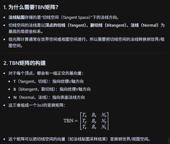
法線貼圖的“藍色”就代表“正對表面外”,紅色/綠色代表“沿U/V方向偏轉”,整個流程無非就是:法線貼圖以RGB值來記錄對法線方向的干擾,這個干擾是在切線空間中進行的,我們還需要TBN矩陣——這個工具來將變換后的法線映射回世界坐標系中。
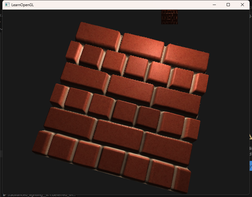
效果如圖:
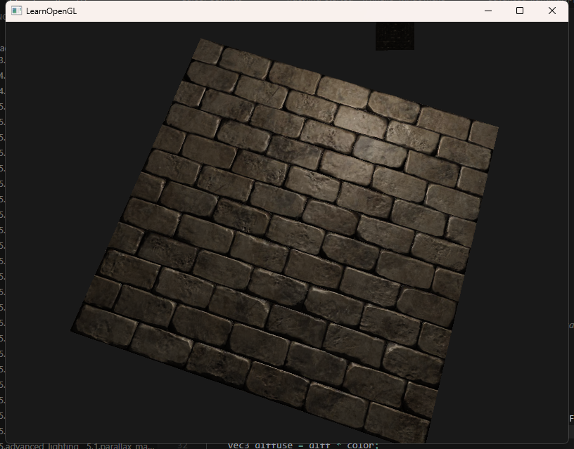
看起來確實有凹凸不平的質感——但其實,這只是薄薄的一個平面生成的效果。
Parallax Mapping
視差貼圖和法線貼圖類似也是也是不改變物體實際幾何形狀的前提下去修改視覺效果,可是和法線貼圖直接去修改法線方向不同,視差貼圖通過動態偏移紋理坐標實現高度不同的視覺效果。
vec2 ParallaxMapping(vec2 texCoords, vec3 viewDir)
{ float height =  texture(depthMap, texCoords).r;     return texCoords - viewDir.xy * (height * heightScale);
}void main()
{           // offset texture coordinates with Parallax Mappingvec3 viewDir = normalize(fs_in.TangentViewPos - fs_in.TangentFragPos);vec2 texCoords = fs_in.TexCoords;texCoords = ParallaxMapping(fs_in.TexCoords,  viewDir);       if(texCoords.x > 1.0 || texCoords.y > 1.0 || texCoords.x < 0.0 || texCoords.y < 0.0)discard;// obtain normal from normal mapvec3 normal = texture(normalMap, texCoords).rgb;normal = normalize(normal * 2.0 - 1.0);   // get diffuse colorvec3 color = texture(diffuseMap, texCoords).rgb;// ambientvec3 ambient = 0.1 * color;// diffusevec3 lightDir = normalize(fs_in.TangentLightPos - fs_in.TangentFragPos);float diff = max(dot(lightDir, normal), 0.0);vec3 diffuse = diff * color;// specular    vec3 reflectDir = reflect(-lightDir, normal);vec3 halfwayDir = normalize(lightDir + viewDir);  float spec = pow(max(dot(normal, halfwayDir), 0.0), 32.0);vec3 specular = vec3(0.2) * spec;FragColor = vec4(ambient + diffuse + specular, 1.0);
}
可以看到我們的視差貼圖會根據深度貼圖的R值來修改原來紋理坐標,在片元著色器的執行流程中,我們的紋理會根據視線方向來動態地調整根據深度貼圖的R值修改過的紋理坐標,從而達到視覺落差的效果。
說起來當然很簡單,但是其背后的工作原理呢?
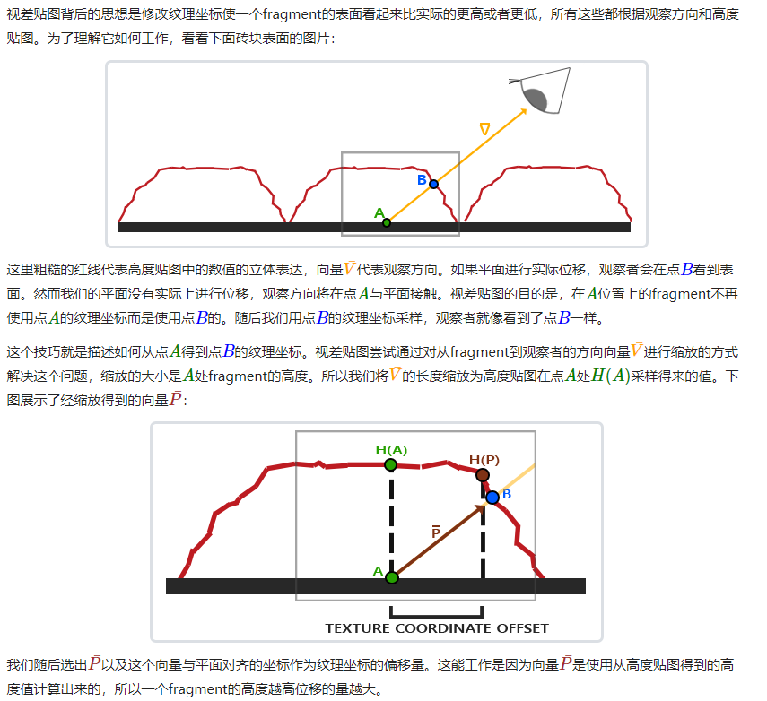
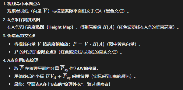
移花接木,貍貓換太子,臥槽這個視差貼圖怎么這么壞啊。?用比較簡單的話來說就是:首先我們的視線看向這個片元時,視線真正與物體表面的交點在A點,但是我們在A點的著色渲染成B點的顏色的話,不就實現了紋理坐標的偏移,從而實現視覺落差的效果了。這個B點是怎么得到的呢?就是根據我們的視差貼圖修改該片元的高度值后與視線相交得到的。
陡峭視差映射(Steep Parallax Mapping)是視差映射的擴展,原則是一樣的,但不是使用一個樣本而是多個樣本來確定向量。即使在陡峭的高度變化的情況下,它也能得到更好的結果,原因在于該技術通過增加采樣的數量提高了精確性。
陡峭視差映射的基本思想是將總深度范圍劃分為同一個深度/高度的多個層。從每個層中我們沿著向量方向移動采樣紋理坐標,直到我們找到一個采樣低于當前層的深度值。
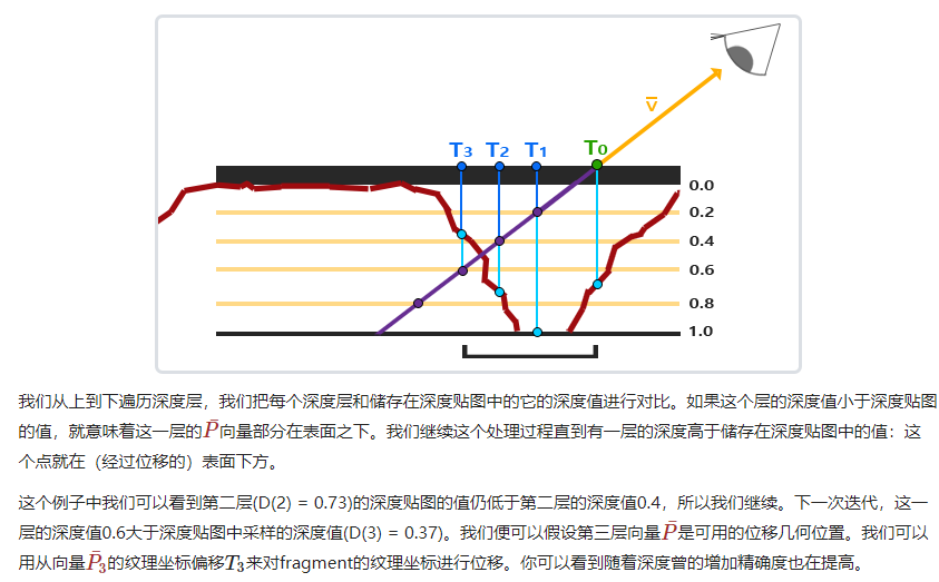
其實就是我們多很多個深度層,然后將視線和這些深度層的交點與深度貼圖的深度值一一比較,找到第一個符合深度貼圖的深度大于交點深度值的深度層,把這個深度層與視線的交點對于的深度值作為我們的紋理顏色渲染對象即可。
代碼上這樣改動:
vec2 ParallaxMapping(vec2 texCoords, vec3 viewDir)
{ // number of depth layersconst float minLayers = 8;const float maxLayers = 32;float numLayers = mix(maxLayers, minLayers, abs(dot(vec3(0.0, 0.0, 1.0), viewDir))); // calculate the size of each layerfloat layerDepth = 1.0 / numLayers;// depth of current layerfloat currentLayerDepth = 0.0;// the amount to shift the texture coordinates per layer (from vector P)vec2 P = viewDir.xy / viewDir.z * heightScale; vec2 deltaTexCoords = P / numLayers;// get initial valuesvec2 currentTexCoords = texCoords;float currentDepthMapValue = texture(depthMap, currentTexCoords).r;while(currentLayerDepth < currentDepthMapValue){// shift texture coordinates along direction of PcurrentTexCoords -= deltaTexCoords;// get depthmap value at current texture coordinatescurrentDepthMapValue = texture(depthMap, currentTexCoords).r; // get depth of next layercurrentLayerDepth += layerDepth; }return currentTexCoords;
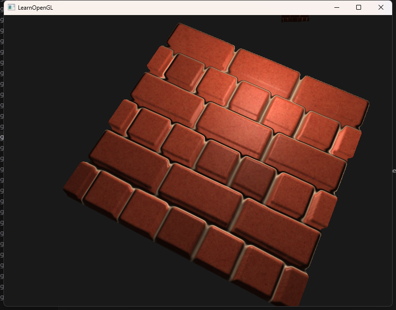
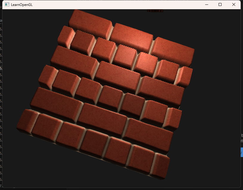
}效果如圖:
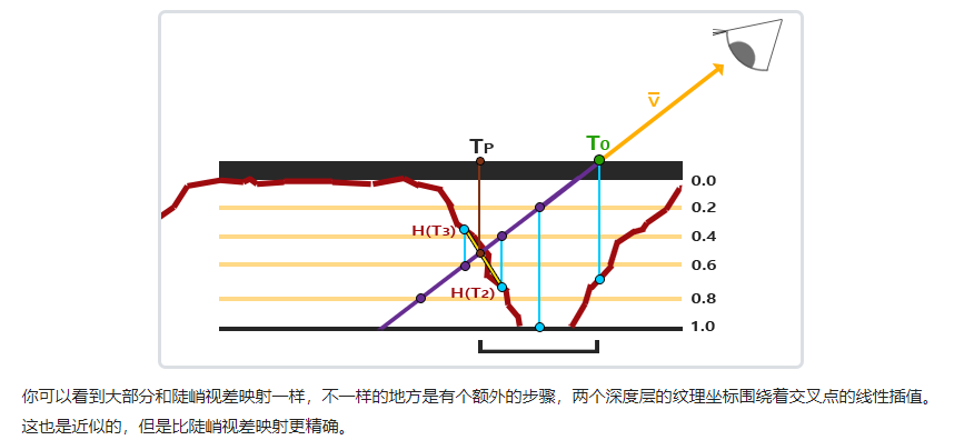
在這個基礎上可以實現效果更好的視差遮蔽映射(Parallax Occlusion Mapping),只需要多加一個線性插值的操作即可。
vec2 ParallaxMapping(vec2 texCoords, vec3 viewDir)
{ // number of depth layersconst float minLayers = 8;const float maxLayers = 32;float numLayers = mix(maxLayers, minLayers, abs(dot(vec3(0.0, 0.0, 1.0), viewDir)));  // calculate the size of each layerfloat layerDepth = 1.0 / numLayers;// depth of current layerfloat currentLayerDepth = 0.0;// the amount to shift the texture coordinates per layer (from vector P)vec2 P = viewDir.xy / viewDir.z * heightScale; vec2 deltaTexCoords = P / numLayers;// get initial valuesvec2  currentTexCoords     = texCoords;float currentDepthMapValue = texture(depthMap, currentTexCoords).r;while(currentLayerDepth < currentDepthMapValue){// shift texture coordinates along direction of PcurrentTexCoords -= deltaTexCoords;// get depthmap value at current texture coordinatescurrentDepthMapValue = texture(depthMap, currentTexCoords).r;  // get depth of next layercurrentLayerDepth += layerDepth;  }// get texture coordinates before collision (reverse operations)vec2 prevTexCoords = currentTexCoords + deltaTexCoords;// get depth after and before collision for linear interpolationfloat afterDepth  = currentDepthMapValue - currentLayerDepth;float beforeDepth = texture(depthMap, prevTexCoords).r - currentLayerDepth + layerDepth;// interpolation of texture coordinatesfloat weight = afterDepth / (afterDepth - beforeDepth);vec2 finalTexCoords = prevTexCoords * weight + currentTexCoords * (1.0 - weight);return finalTexCoords;
}
效果如圖:
HDR
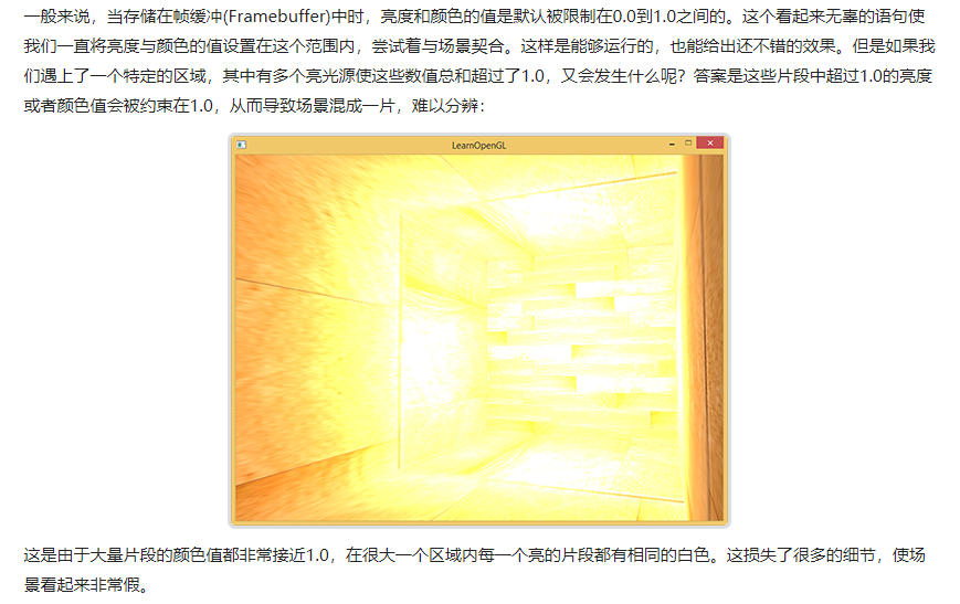
上來都是一些介紹HDR高動態范圍概念的文字,我覺得這個翻譯實在廢話有點多,說白了HDR就是解決攝像設備里人為設置的亮度范圍導致的過亮或者過暗時丟失的細節的機制:它允許你短暫地突破這個亮度范圍,在捕獲到細節后再將這些帶有細節的圖像融合在一起之后調整亮度到范圍內。
很好,明白原理之后讓我們深入細節。
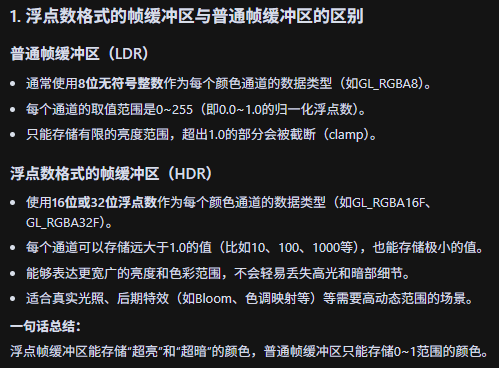
首先我們需要一個浮點數類型的幀緩沖:
// 創建浮點幀緩沖
unsigned int hdrFBO;
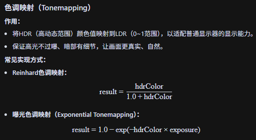
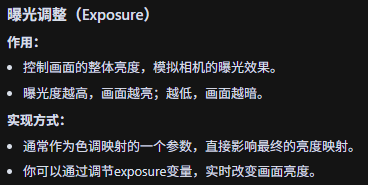
glGenFramebuffers(1, &hdrFBO);然后我們還涉及到色調映射(Tonemapping)和曝光調整(Exposure)。
// 2. now render floating point color buffer to 2D quad and tonemap HDR colors to default framebuffer's (clamped) color range
hdrShader.use();
glActiveTexture(GL_TEXTURE0);
glBindTexture(GL_TEXTURE_2D, colorBuffer);
hdrShader.setInt("hdr", hdr);
hdrShader.setFloat("exposure", exposure);
renderQuad();
#version 330 core
out vec4 FragColor;in vec2 TexCoords;uniform sampler2D hdrBuffer; // HDR幀緩沖的顏色紋理
uniform bool hdr; // 是否啟用HDR色調映射
uniform float exposure; // 曝光度void main()
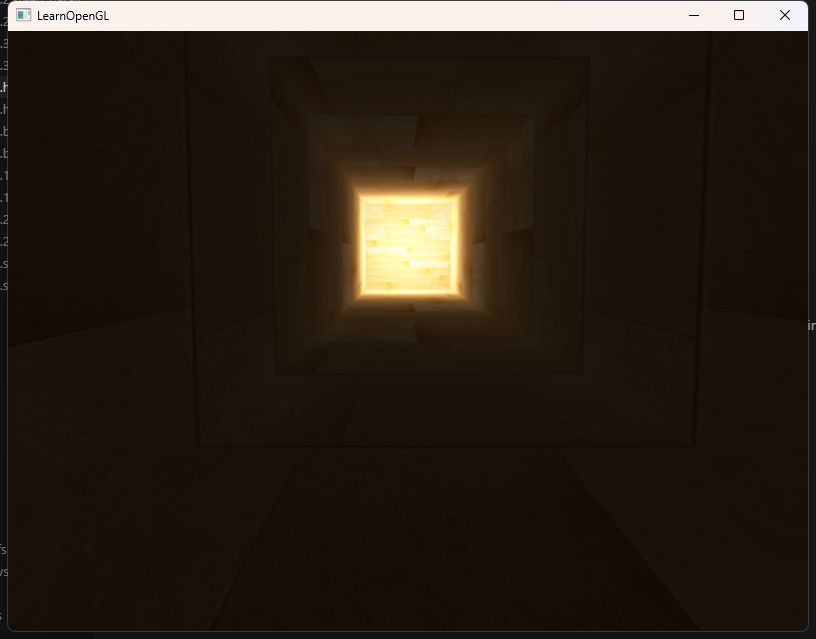
{ const float gamma = 2.2;vec3 hdrColor = texture(hdrBuffer, TexCoords).rgb; // 采樣HDR顏色if(hdr){// Reinhard色調映射(被注釋掉了)// vec3 result = hdrColor / (hdrColor + vec3(1.0));// 曝光色調映射vec3 result = vec3(1.0) - exp(-hdrColor * exposure);// Gamma校正result = pow(result, vec3(1.0 / gamma));FragColor = vec4(result, 1.0);}else{// 只做Gamma校正,不做色調映射vec3 result = pow(hdrColor, vec3(1.0 / gamma));FragColor = vec4(result, 1.0);}
}效果如圖:

:未命名的命名空間)


)


)


