Features
特征
This library contained in BRepFeat package is necessary for creation and manipulation of form and mechanical features that go beyond the classical boundary representation of shapes. In that sense, BRepFeat is an extension of BRepBuilderAPI package.
包含在 BRepFeat 包中的該庫,用于創建和操作超出形狀經典邊界表示的形狀特征和機械特征。從這個意義上講,BRepFeat 是 BRepBuilderAPI 包的擴展。
Form Features
形狀特征
The form features are depressions or protrusions including the following types:
形狀特征是指凹坑或凸起,包括以下類型:
- Cylinder;
圓柱體; - Draft Prism;
拔模棱柱; - Prism;
棱柱; - Revolved feature;
旋轉特征; - Pipe.
管道。
Depending on whether you wish to make a depression or a protrusion, you can choose either to remove matter (Boolean cut: Fuse equal to 0) or to add it (Boolean fusion: Fuse equal to 1).
根據需要創建凹坑或凸起,可選擇去除材料(布爾切割:Fuse等于0)或添加材料(布爾融合:Fuse等于1)。
The semantics of form feature creation is based on the construction of shapes:
形狀特征創建的語義基于以下形狀構造方式:
- for a certain length in a certain direction;
在特定方向上延伸特定長度; - up to the limiting face;
延伸至限制面; - from the limiting face at a height;
從限制面起按高度延伸; - above and/or below a plane.
在平面上方和/或下方。
The shape defining the construction of a feature can be either a supporting edge or a concerned area of a face.
定義特征構造的形狀可以是支撐邊或面的相關區域。
In case of supporting edge, this contour can be attached to a face of the basis shape by binding. When the contour is bound to this face, the information that the contour will slide on the face becomes available to the relevant class methods. In case of the concerned area of a face, you can, for example, cut it out and move it at a different height, which defines the limiting face of a protrusion or depression.
Topological definition with local operations of this sort makes calculations simpler and faster than a global operation. The latter would entail a second phase of removing unwanted matter to get the same result.
The Form from BRepFeat package is a deferred class used as a root for form features. It inherits MakeShape from BRepBuilderAPI and provides implementation of methods keep track of all sub-shapes.
在支撐邊的情況下,該輪廓可通過綁定方式附著到基礎形狀的某個面上。當此輪廓綁定到該面時,“輪廓將在面上滑動” 的信息便可供相關類方法使用。對于面的相關區域,例如可將其切割出來并在不同高度移動,這定義了凸起或凹陷的限制面。
這種通過局部操作進行的拓撲定義,使得計算相比全局操作更為簡單且快速。后者需要通過第二階段去除多余部分才能獲得相同結果。
BRepFeat 包中的 Form 是一個延遲類,用作形狀特征的根類。它從 BRepBuilderAPI 繼承了 MakeShape,并提供了用于跟蹤所有子形狀的方法實現。
Prism
The class BRepFeat_MakePrism is used to build a prism interacting with a shape. It is created or initialized from
BRepFeat_MakePrism 類用于構建與形狀交互的棱柱體。其創建或初始化基于以下參數:
- a shape (the basic shape),
一個形狀(基礎形狀), - the base of the prism,
棱柱的底面, - a face (the face of sketch on which the base has been defined and used to determine whether the base has been defined on the basic shape or not),
一個面(草圖所在的面,底面在此面上定義,用于判斷底面是否定義在基礎形狀上), - a direction,
一個方向, - a Boolean indicating the type of operation (fusion=protrusion or cut=depression) on the basic shape,
一個布爾值,指示對基礎形狀執行的操作類型(融合=凸起或切割=凹陷), - another Boolean indicating if the self-intersections have to be found (not used in every case).
另一個布爾值,指示是否需要查找自相交(非所有情況均使用)。
There are six Perform methods:
共有六種 Perform 方法:
| Method | Description |
|---|---|
| Perform(Height) | 生成的棱柱具有給定的長度。 |
| Perform(Until) | 棱柱定義于底面位置與給定面之間。 |
| Perform(From, Until) | 棱柱定義于兩個面 From 和 Until 之間。 |
| PerformUntilEnd() | 棱柱為半無限延伸,由底面的實際位置限制。 |
| PerformFromEnd(Until) | 棱柱為半無限延伸,由面 Until 限制。 |
| PerformThruAll() | 棱柱為無限延伸。若為凹陷操作,結果類似用無限棱柱切割;若為凸起操作,結果不保留無限部分。 |
Note that Add method can be used before Perform methods to indicate that a face generated by an edge slides onto a face of the base shape.
注意:可在調用 Perform 方法前使用 Add 方法,用于指示邊生成的面在基礎形狀的面上滑動。
代碼示例
以下代碼執行凸起操作(即將形狀的面轉換為棱柱):
TopoDS_Shape Sbase = ...;  // 初始形狀
TopoDS_Face Fbase = ....; // 棱柱底面  gp_Dir Extrusion (.,.,.);  //  extrusion 方向  // 傳入空面作為草圖面
BRepFeat_MakePrism thePrism(Sbase, Fbase, TopoDS_Face(),  Extrusion, Standard_True, Standard_True);  thePrism.Perform(100.);  // 執行高度為100的棱柱操作
if (thePrism.IsDone()) {  TopoDS_Shape theResult = thePrism;  // 后續處理  ...
}

Fusion with MakePrism
使用 MakePrism 進行融合操作

Creating a prism between two faces with Perform()
通過 Perform() 方法在兩個面之間創建棱柱體
Draft Prism
拔模棱柱
The class BRepFeat_MakeDPrism is used to build draft prism topologies interacting with a basis shape. These can be depressions or protrusions. A class object is created or initialized from:
BRepFeat_MakeDPrism 類用于構建與基礎形狀交互的拔模棱柱拓撲結構,可實現凹陷或凸起特征。類對象通過以下參數創建或初始化:
- a shape (basic shape),
一個形狀(基礎形狀), - the base of the prism,
棱柱的底面, - a face (face of sketch on which the base has been defined and used to determine whether the base has been defined on the basic shape or not),
一個面(草圖所在的面,底面在此面上定義,用于判斷底面是否定義在基礎形狀上), - an angle,
一個角度, - a Boolean indicating the type of operation (fusion=protrusion or cut=depression) on the basic shape,
一個布爾值,指示對基礎形狀執行的操作類型(融合=凸起或切割=凹陷), - another Boolean indicating if self-intersections have to be found (not used in every case).
另一個布爾值,指示是否需要查找自相交(非所有情況均使用)。
Evidently, the input data for MakeDPrism are the same as for MakePrism except for a new parameter Angle and a missing parameter Direction: the direction of the prism generation is determined automatically as the normal to the base of the prism. The semantics of draft prism feature creation is based on the construction of shapes:
顯然,除新增參數 Angle 和移除參數 Direction 外,MakeDPrism 的輸入數據與 MakePrism 一致。棱柱生成方向自動確定為底面的法線方向。拔模棱柱特征的創建語義基于以下形狀構造方式:
- along a length
沿指定長度 - up to a limiting face
延伸至限制面 - from a limiting face to a height
從限制面到指定高度
The shape defining construction of the draft prism feature can be either the supporting edge or the concerned area of a face.
拔模棱柱特征的形狀定義方式包括支撐邊或面的相關區域:
In case of the supporting edge, this contour can be attached to a face of the basis shape by binding. When the contour is bound to this face, the information that the contour will slide on the face becomes available to the relevant class methods.
當使用支撐邊時,輪廓可通過綁定附加到基礎形狀的面上。當輪廓綁定到該面后,相關類方法將獲取“輪廓在面上滑動”的信息。
In case of the concerned area of a face, it is possible to cut it out and move it to a different height, which will define the limiting face of a protrusion or depression direction.
當使用面的相關區域時,可將其切割并移動到不同高度,從而定義凸起或凹陷方向的限制面。
The Perform methods are the same as for MakePrism.
Perform 方法與 MakePrism 完全一致。
代碼示例:創建 tapered prism(錐形棱柱)
// 初始化基礎形狀(創建長方體)
TopoDS_Shape S = BRepPrimAPI_MakeBox(400., 250., 300.); // 遍歷獲取目標面(此處通過Explorer獲取第5個面)
TopExp_Explorer Ex;
Ex.Init(S, TopAbs_FACE);
Ex.Next(); Ex.Next(); Ex.Next(); Ex.Next(); Ex.Next();
TopoDS_Face F = TopoDS::Face(Ex.Current()); // 提取面的幾何曲面
Handle(Geom_Surface) surf = BRep_Tool::Surface(F); // 定義2D圓輪廓(圓心(200,130),半徑50,X軸方向)
gp_Circ2d c(gp_Ax2d(gp_Pnt2d(200., 130.), gp_Dir2d(1., 0.)), 50.); // 構建2D輪廓線(半圓+半圓閉合)
BRepBuilderAPI_MakeWire MW;
Handle(Geom2d_Curve) aline = new Geom2d_Circle(c);
MW.Add(BRepBuilderAPI_MakeEdge(aline, surf, 0., PI));
MW.Add(BRepBuilderAPI_MakeEdge(aline, surf, PI, 2.*PI)); // 基于曲面和輪廓構建面
BRepBuilderAPI_MakeFace MKF;
MKF.Init(surf, Standard_False);
MKF.Add(MW.Wire());
TopoDS_Face FP = MKF.Face();
BRepLib::BuildCurves3d(FP); // 創建拔模棱柱操作(參數:基礎形狀、底面、草圖面、角度10°、凸起操作、啟用自相交檢測)
BRepFeat_MakeDPrism MKDP (S, FP, F, 10*PI/180, Standard_True, Standard_True);
MKDP.Perform(200);  // 執行高度為200的拔模操作
TopoDS_Shape res1 = MKDP.Shape();  // 獲取結果形狀

Revolution
旋轉特征
The class BRepFeat_MakeRevol is used to build a revolution interacting with a shape. It is created or initialized from:
BRepFeat_MakeRevol 類用于構建與形狀交互的旋轉特征。其創建或初始化參數如下:
- a shape (the basic shape,)
一個形狀(基礎形狀), - the base of the revolution,
旋轉的底面, - a face (the face of sketch on which the base has been defined and used to determine whether the base has been defined on the basic shape or not),
一個面(草圖所在的面,底面在此面上定義,用于判斷底面是否定義在基礎形狀上), - an axis of revolution,
旋轉軸, - a boolean indicating the type of operation (fusion=protrusion or cut=depression) on the basic shape,
一個布爾值,指示對基礎形狀執行的操作類型(融合=凸起或切割=凹陷), - another boolean indicating whether the self-intersections have to be found (not used in every case).
另一個布爾值,指示是否需要查找自相交(非所有情況均使用)。
Perform 方法
There are four Perform methods:
共有四種 Perform 方法:
| Method | Description |
|---|---|
| Perform(Angle) | 生成指定角度大小的旋轉特征。 |
| Perform(Until) | 旋轉范圍定義為從底面當前位置到給定面之間。 |
| Perform(From, Until) | 旋轉范圍定義為兩個面 From 和 Until 之間。 |
| PerformThruAll() | 結果類似于 Perform(2*PI),即完整旋轉一周。 |
Note that Add method can be used before Perform methods to indicate that a face generated by an edge slides onto a face of the base shape.
注意:可在調用 Perform 方法前使用 Add 方法,用于指示邊生成的面在基礎形狀的面上滑動。
代碼示例:旋轉操作(受限面限制)
TopoDS_Shape Sbase = ...;  // 初始形狀
TopoDS_Face Frevol = ....; // 旋轉底面
TopoDS_Face FUntil = ....; // 限制旋轉的面  gp_Dir RevolDir (.,.,.);  // 旋轉方向
gp_Ax1 RevolAx(gp_Pnt(.,.,.), RevolDir);  // 旋轉軸  // 傳入空面作為草圖面
BRepFeat_MakeRevol theRevol(Sbase, Frevol, TopoDS_Face(), RevolAx, Standard_True, Standard_True);  theRevol.Perform(FUntil);  // 執行旋轉直到FUntil面
if (theRevol.IsDone()) {  TopoDS_Shape theResult = theRevol;  // 后續處理  ...
}
Pipe
管道特征
The class BRepFeat_MakePipe constructs compound shapes with pipe features: depressions or protrusions. A class object is created or initialized from:
BRepFeat_MakePipe 類用于構建帶有管道特征的復合形狀(凹陷或凸起)。其創建或初始化參數如下:
- a shape (basic shape),
一個形狀(基礎形狀), - a base face (profile of the pipe)
一個底面(管道截面輪廓), - a face (face of sketch on which the base has been defined and used to determine whether the base has been defined on the basic shape or not),
一個面(草圖所在的面,底面在此面上定義,用于判斷底面是否定義在基礎形狀上), - a spine wire
一條路徑線(管道中心線), - a Boolean indicating the type of operation (fusion=protrusion or cut=depression) on the basic shape,
一個布爾值,指示對基礎形狀執行的操作類型(融合=凸起或切割=凹陷), - another Boolean indicating if self-intersections have to be found (not used in every case).
另一個布爾值,指示是否需要查找自相交(非所有情況均使用)。
Perform 方法
There are three Perform methods:
共有三種 Perform 方法:
| Method | Description |
|---|---|
| Perform() | 管道沿整個路徑線(中心線)定義。 |
| Perform(Until) | 管道沿路徑延伸直到給定面。 |
| Perform(From, Until) | 管道定義在兩個面 From 和 Until 之間。 |
代碼示例:創建管道特征
// 創建基礎形狀(長方體)
TopoDS_Shape S = BRepPrimAPI_MakeBox(400., 250., 300.); // 遍歷獲取目標面(第2個面)
TopExp_Explorer Ex;
Ex.Init(S, TopAbs_FACE);
Ex.Next(); Ex.Next();
TopoDS_Face F1 = TopoDS::Face(Ex.Current());
Handle(Geom_Surface) surf = BRep_Tool::Surface(F1); // 構建管道截面輪廓(三角形)
BRepBuilderAPI_MakeWire MW1;
gp_Pnt2d p1, p2; // 第一條邊
p1 = gp_Pnt2d(100., 100.);
p2 = gp_Pnt2d(200., 100.);
Handle(Geom2d_Line) aline = GCE2d_MakeLine(p1, p2).Value();
MW1.Add(BRepBuilderAPI_MakeEdge(aline, surf, 0., p1.Distance(p2))); // 第二條邊
p1 = p2;
p2 = gp_Pnt2d(150., 200.);
aline = GCE2d_MakeLine(p1, p2).Value();
MW1.Add(BRepBuilderAPI_MakeEdge(aline, surf, 0., p1.Distance(p2))); // 第三條邊(閉合三角形)
p1 = p2;
p2 = gp_Pnt2d(100., 100.);
aline = GCE2d_MakeLine(p1, p2).Value();
MW1.Add(BRepBuilderAPI_MakeEdge(aline, surf, 0., p1.Distance(p2))); // 基于曲面和輪廓構建面
BRepBuilderAPI_MakeFace MKF1;
MKF1.Init(surf, Standard_False);
MKF1.Add(MW1.Wire());
TopoDS_Face FP = MKF1.Face();
BRepLib::BuildCurves3d(FP); // 定義管道路徑線(貝塞爾曲線)
TColgp_Array1OfPnt CurvePoles(1, 3);
gp_Pnt pt = gp_Pnt(150., 0., 150.);
CurvePoles(1) = pt;
pt = gp_Pnt(200., 100., 150.);
CurvePoles(2) = pt;
pt = gp_Pnt(150., 200., 150.);
CurvePoles(3) = pt; Handle(Geom_BezierCurve) curve = new Geom_BezierCurve(CurvePoles);
TopoDS_Edge E = BRepBuilderAPI_MakeEdge(curve);
TopoDS_Wire W = BRepBuilderAPI_MakeWire(E); // 創建管道特征(參數:基礎形狀、截面輪廓、草圖面、路徑線、切割操作、啟用自相交檢測)
BRepFeat_MakePipe MKPipe (S, FP, F1, W, Standard_False, Standard_True);
MKPipe.Perform();  // 執行管道操作
TopoDS_Shape res1 = MKPipe.Shape();  // 獲取結果形狀

Mechanical Features
機械特征
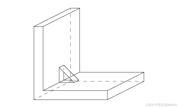
Mechanical features include ribs, protrusions and grooves (or slots), depressions along planar (linear) surfaces or revolution surfaces.
機械特征包括筋、凸起、凹槽(或槽)以及沿平面(線性)表面或旋轉表面的凹陷。
The semantics of mechanical features is built around giving thickness to a contour. This thickness can either be symmetrical – on one side of the contour – or dissymmetrical – on both sides. As in the semantics of form features, the thickness is defined by construction of shapes in specific contexts.
機械特征的語義核心是為輪廓賦予厚度。厚度可以是對稱的(位于輪廓一側)或不對稱的(位于兩側)。與形狀特征類似,厚度通過在特定上下文中構造形狀來定義。
The development contexts differ, however, in the case of mechanical features. Here they include extrusion:
然而,機械特征的構建上下文有所不同,包括以下拉伸方式:
- to a limiting face of the basis shape;
到基礎形狀的限制面; - to or from a limiting plane;
到或從限制平面; - to a height.
到指定高度。
類初始化參數
A class object is created or initialized from:
類對象通過以下參數創建或初始化:
- a shape (basic shape);
一個形狀(基礎形狀); - a wire (base of rib or groove);
一條線(筋或槽的基礎輪廓); - a plane (plane of the wire);
一個平面(輪廓所在的平面); - direction1 (a vector along which thickness will be built up);
方向1(厚度增加的方向向量); - direction2 (vector opposite to the previous one along which thickness will be built up, may be null);
方向2(與方向1相反的方向向量,厚度增加方向,可為空); - a Boolean indicating the type of operation (fusion=rib or cut=groove) on the basic shape;
一個布爾值,指示對基礎形狀執行的操作類型(融合=筋或切割=槽); - another Boolean indicating if self-intersections have to be found (not used in every case).
另一個布爾值,指示是否需要查找自相交(非所有情況均使用)。
Linear Form
線性形狀
Linear form is implemented in MakeLinearForm class, which creates a rib or a groove along a planar surface. There is one Perform() method, which performs a prism from the wire along the direction1 and direction2 interacting with base shape Sbase. The height of the prism is Magnitude(Direction1)+Magnitude(direction2).
線性形狀由 MakeLinearForm 類實現,用于沿平面創建筋或槽。該類有一個 Perform() 方法,沿 direction1 和 direction2 方向從輪廓線創建棱柱,并與基礎形狀 Sbase 交互。棱柱高度為 Direction1 長度與 Direction2 長度之和。
代碼示例:創建筋特征
// 構建基礎輪廓線(六邊形)
BRepBuilderAPI_MakeWire mkw;
gp_Pnt p1 = gp_Pnt(0., 0., 0.);
gp_Pnt p2 = gp_Pnt(200., 0., 0.);
mkw.Add(BRepBuilderAPI_MakeEdge(p1, p2)); p1 = p2;
p2 = gp_Pnt(200., 0., 50.);
mkw.Add(BRepBuilderAPI_MakeEdge(p1, p2)); p1 = p2;
p2 = gp_Pnt(50., 0., 50.);
mkw.Add(BRepBuilderAPI_MakeEdge(p1, p2)); p1 = p2;
p2 = gp_Pnt(50., 0., 200.);
mkw.Add(BRepBuilderAPI_MakeEdge(p1, p2)); p1 = p2;
p2 = gp_Pnt(0., 0., 200.);
mkw.Add(BRepBuilderAPI_MakeEdge(p1, p2)); p1 = p2;
mkw.Add(BRepBuilderAPI_MakeEdge(p2, gp_Pnt(0., 0., 0.))); // 基于輪廓創建基礎形狀(拉伸為棱柱)
TopoDS_Shape S = BRepBuilderAPI_MakePrism(BRepBuilderAPI_MakeFace(mkw.Wire()), gp_Vec(gp_Pnt(0., 0., 0.), gp_Pnt(0., 100., 0.))
); // 定義筋的輪廓線(斜線段)
TopoDS_Wire W = BRepBuilderAPI_MakeWire(BRepBuilderAPI_MakeEdge(gp_Pnt(50., 45., 100.), gp_Pnt(100., 45., 50.))
); // 定義輪廓所在平面
Handle(Geom_Plane) aplane = new Geom_Plane(gp_Pnt(0., 45., 0.), gp_Vec(0., 1., 0.)
); // 創建線性形狀特征(參數:基礎形狀、輪廓線、平面、方向1、方向2、操作類型、自相交檢測)
BRepFeat_MakeLinearForm aform(S, W, aplane, gp_Dir(0., 5., 0.),  // 正向厚度方向(Y軸正方向)gp_Dir(0., -3., 0.), // 負向厚度方向(Y軸負方向)1, Standard_True     // 操作類型:融合(創建筋)
); aform.Perform();  // 執行操作
TopoDS_Shape res = aform.Shape();  // 獲取結果形狀
Gluer
粘合器
The class BRepFeat_Gluer allows gluing two solids along faces. The contact faces of the glued shape must not have parts outside the contact faces of the basic shape. Upon completion the algorithm gives the glued shape with cut out parts of faces inside the shape.
BRepFeat_Gluer 類用于沿面粘合兩個實體。被粘合形狀的接觸面不得超出基礎形狀的接觸面范圍。算法執行完畢后,粘合形狀會剪切掉內部的面部分。
The class is created or initialized from two shapes: the “glued” shape and the basic shape (on which the other shape is glued). Two Bind methods are used to bind a face of the glued shape to a face of the basic shape and an edge of the glued shape to an edge of the basic shape.
該類通過兩個形狀創建或初始化:“被粘合”形狀和基礎形狀(另一個形狀粘合到基礎形狀上)。使用兩種 Bind 方法將被粘合形狀的面綁定到基礎形狀的面,以及將被粘合形狀的邊綁定到基礎形狀的邊。
Note that every face and edge has to be bounded, if two edges of two glued faces are coincident they must be explicitly bounded.
請注意,每個面和邊必須是有界的;如果兩個粘合面的邊重合,必須顯式界定。
代碼示例:粘合兩個形狀
TopoDS_Shape Sbase = ...; // 基礎形狀
TopoDS_Shape Sglued = ...; // 被粘合形狀 TopTools_ListOfShape Lfbase;
TopTools_ListOfShape Lfglued;
// 確定粘合面
... BRepFeat_Gluer theGlue(Sglued, Sbase);
TopTools_ListIteratorOfListOfShape itlb(Lfbase);
TopTools_ListIteratorOfListOfShape itlg(Lfglued);
for (; itlb.More(); itlb.Next(), itlg.Next()) { const TopoDS_Face& f1 = TopoDS::Face(itlg.Value()); const TopoDS_Face& f2 = TopoDS::Face(itlb.Value()); theGlue.Bind(f1, f2); // 綁定面// 例如,使用LocOpe中的FindEdges類確定重合邊LocOpe_FindEdge fined(f1, f2); for (fined.InitIterator(); fined.More(); fined.Next()) { theGlue.Bind(fined.EdgeFrom(), fined.EdgeTo()); // 綁定邊}
}
theGlue.Build(); // 執行粘合
if (theGlue.IsDone()) { TopoDS_Shape theResult = theGlue; ...
}
Split Shape
形狀分割
The class BRepFeat_SplitShape is used to split faces of a shape into wires or edges. The shape containing the new entities is rebuilt, sharing the unmodified ones.
BRepFeat_SplitShape 類用于將形狀的面分割為線框或邊。包含新實體的形狀會被重建,并共享未修改的實體。
The class is created or initialized from a shape (the basic shape). Three Add methods are available:
該類通過一個形狀(基礎形狀)創建或初始化,提供三種 Add 方法:
- Add(Wire, Face) – adds a new wire on a face of the basic shape.
Add(線框, 面) – 在基礎形狀的面上添加新線框。 - Add(Edge, Face) – adds a new edge on a face of the basic shape.
Add(邊, 面) – 在基礎形狀的面上添加新邊。 - Add(EdgeNew, EdgeOld) – adds a new edge on an existing one (the old edge must contain the new edge).
Add(新邊, 舊邊) – 在現有邊上添加新邊(舊邊必須包含新邊)。
Note: The added wires and edges must define closed wires on faces or wires located between two existing edges. Existing edges must not be intersected.
注意:添加的線框和邊必須在面上定義閉合線框,或位于兩個現有邊之間的線框。現有邊不得相交。
代碼示例:分割面
TopoDS_Shape Sbase = ...; // 基礎形狀
TopoDS_Face Fsplit = ...; // Sbase的面
TopoDS_Wire Wsplit = ...; // 包含在Fsplit中的新線框 BRepFeat_SplitShape Spls(Sbase);
Spls.Add(Wsplit, Fsplit); // 添加線框到面
TopoDS_Shape theResult = Spls;
...


)


