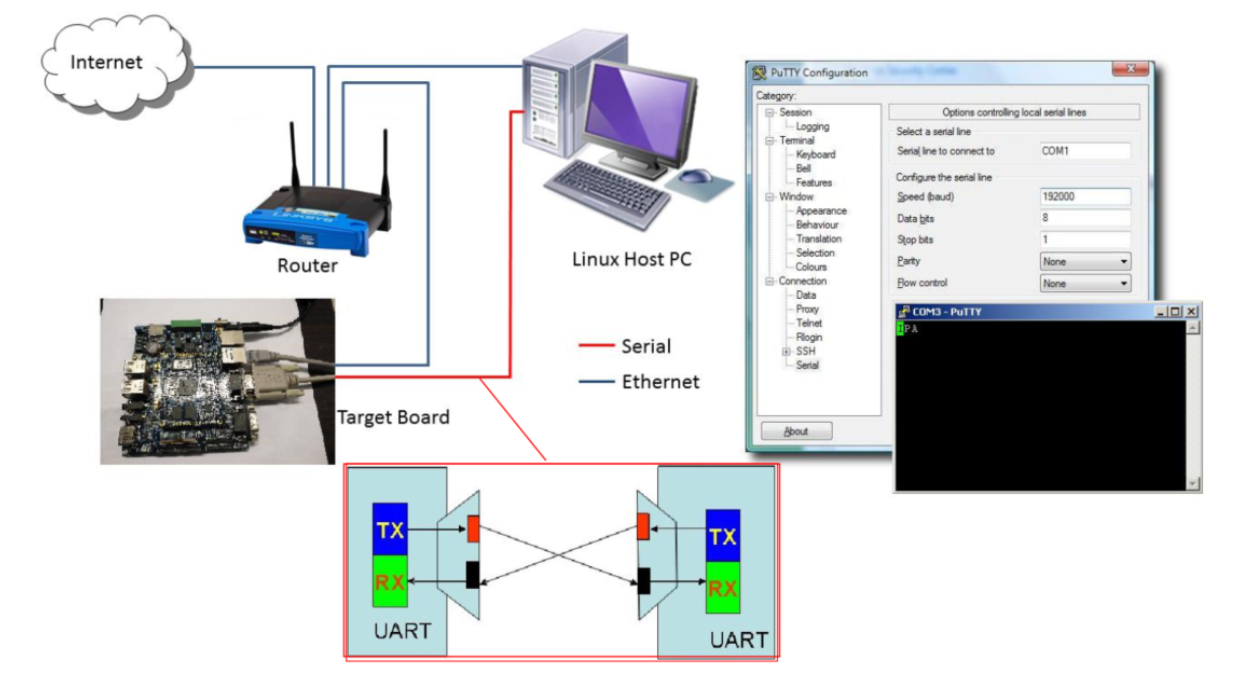
2.1 實驗目的
為os添加uart功能,通過串口實現開發板與PC交互。
2.1 硬件信息
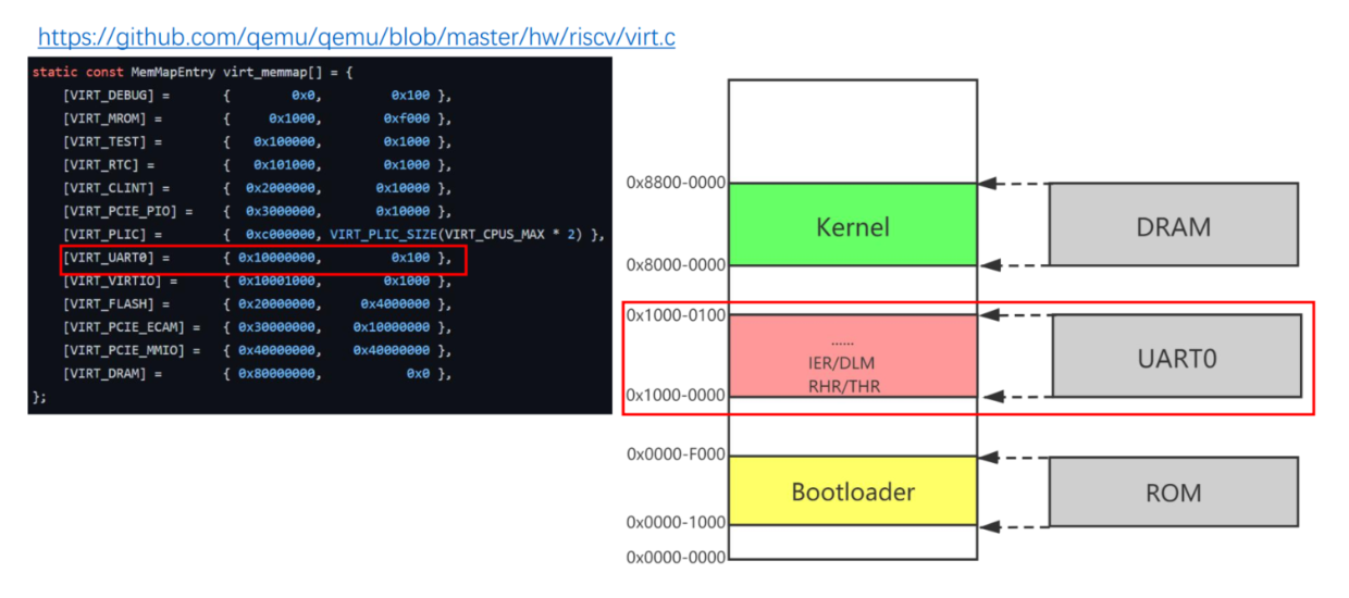
QEMU虛擬SoC含有 虛擬NS16550A設備 。
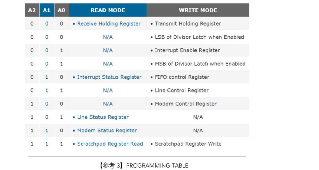
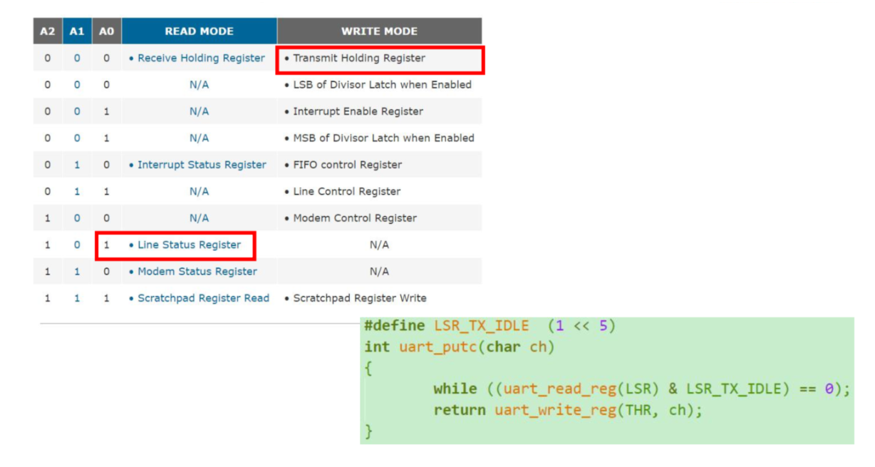
不同的地址線組合(A2、A1、A0)對應的讀寫模式和寄存器如下所示:
2.2 NS16550a 的初始化
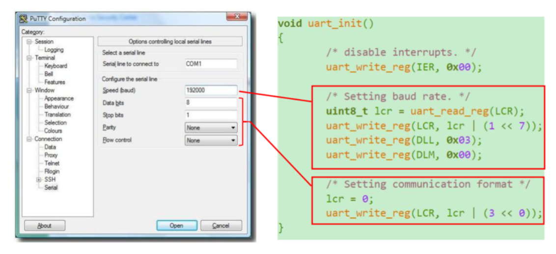
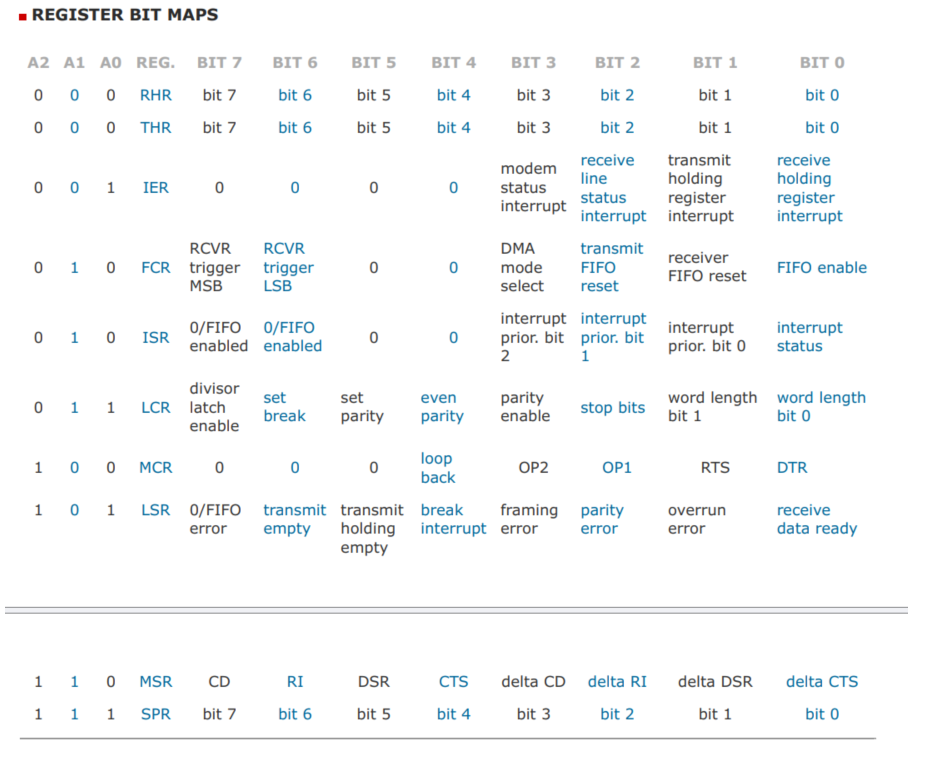
線路控制寄存器(LCR)中的bit7位來實現復用DLL、DLM兩個寄存器拼起來作為16位波特率寄存器。當bit7位被設置為1時,地址0和1用于訪問除數鎖存寄存器(DLL和DLM),用于設置波特率。
- 關閉中斷
- 設置波特率
- 設置異步數據通信格式
void uart_init()
{/* disable interrupts. */uart_write_reg(IER, 0x00);/** Setting baud rate. Just a demo here if we care about the divisor,* but for our purpose [QEMU-virt], this doesn't really do anything.** Notice that the divisor register DLL (divisor latch least) and DLM (divisor* latch most) have the same base address as the receiver/transmitter and the* interrupt enable register. To change what the base address points to, we* open the "divisor latch" by writing 1 into the Divisor Latch Access Bit* (DLAB), which is bit index 7 of the Line Control Register (LCR).** Regarding the baud rate value, see [1] "BAUD RATE GENERATOR PROGRAMMING TABLE".* We use 38.4K when 1.8432 MHZ crystal, so the corresponding value is 3.* And due to the divisor register is two bytes (16 bits), so we need to* split the value of 3(0x0003) into two bytes, DLL stores the low byte,* DLM stores the high byte.*/uint8_t lcr = uart_read_reg(LCR);uart_write_reg(LCR, lcr | (1 << 7));uart_write_reg(DLL, 0x03);uart_write_reg(DLM, 0x00);/** Continue setting the asynchronous data communication format.* - number of the word length: 8 bits* - number of stop bits:1 bit when word length is 8 bits* - no parity* - no break control* - disabled baud latch*/lcr = 0;uart_write_reg(LCR, lcr | (3 << 1));
}
原代碼這里是這樣,感覺不太對,應該是左移一位的。
lcr = 0;
uart_write_reg(LCR, lcr | (3 << 0));
2.3 NS16550a 的數據讀寫
在NS16550A UART中,區分讀寫模式是通過控制信號(如讀/寫控制線)來實現的,而不是通過寄存器地址。這些控制信號通常由CPU或其他主控設備提供。以下是區分讀寫模式的一般步驟:
- 當CPU或其他主控設備想要從UART讀取數據時,它會將讀控制線置為有效狀態(低電平)。同時將芯片選擇信號置為有效狀態,以選中UART設備。
- 當CPU或其他主控設備想要向UART寫入數據時,它會將寫控制線置為有效狀態(低電平)。同樣將芯片選擇信號置為有效狀態,以選中UART設備。

讀:
/** LINE STATUS REGISTER (LSR)* LSR BIT 0:* 0 = no data in receive holding register or FIFO.* 1 = data has been receive and saved in the receive holding register or FIFO.* ......* LSR BIT 5:* 0 = transmit holding register is full. 16550 will not accept any data for transmission.* 1 = transmitter hold register (or FIFO) is empty. CPU can load the next character.* ......*/
#define LSR_RX_READY (1 << 0)
#define LSR_TX_IDLE  (1 << 5)int uart_putc(char ch)
{while ((uart_read_reg(LSR) & LSR_TX_IDLE) == 0);return uart_write_reg(THR, ch);
}void uart_puts(char *s)
{while (*s) {uart_putc(*s++);}
}
寫:
練習 7-2
要求:參考code/os/01-helloRVOS,在此基礎上增加采?輪詢?式讀取控制臺上輸入的字符并 回顯 在控制臺上。另外?戶按下回?后能夠另起??從頭開始。
int uart_getc()
{char ch;while ((uart_read_reg(LSR) & LSR_RX_READY) == 0);ch = uart_read_reg(RHR);return ch;
}void uart_gets(char *s, int len)
{int i = 0;char ch;while (i < len - 1) {ch = uart_getc(); if (ch == '\r') { break;}s[i++] = ch;}s[i] = '\0';
}/*** 回顯功能:讀取用戶輸入并回顯到控制臺*/
void uart_echo()
{char buffer[100]; 	uart_puts("UART Echo Ready:\r\n");while (1) {uart_gets(buffer, sizeof(buffer)); uart_putc('\r'); uart_putc('\n'); uart_puts("--kernel收到數據--\n");uart_puts(buffer);uart_putc('\r'); uart_putc('\n'); }
}最后一定記得在kernel.c添加extern聲明:
extern void uart_echo(void);void start_kernel(void)
{uart_init();uart_puts("Hello, RVOS!\n");uart_echo(); // 開始回顯while (1) {}; // stop here!
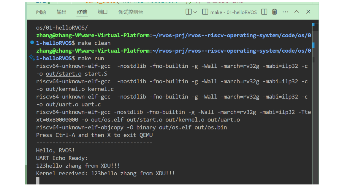
}運行結果:
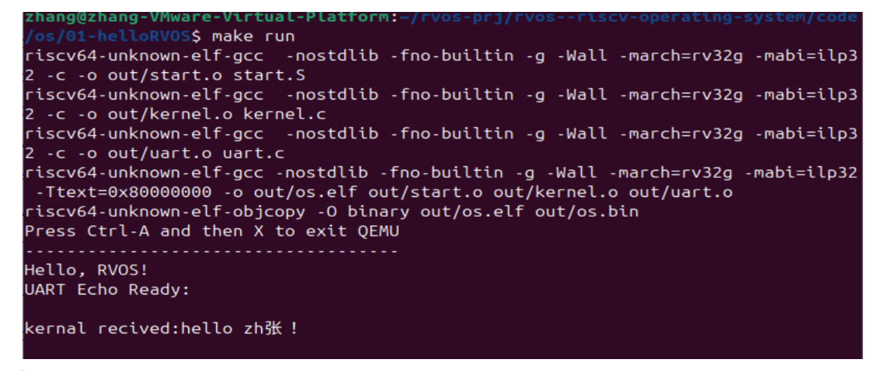
存在一個問題就是在終端輸入的內容無法顯示,且無法刪除。
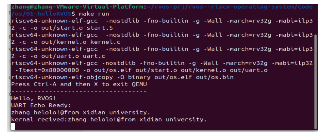
問題解決:在當前實現中,輸入的字符雖然被回顯,但無法正確處理刪除鍵(Backspace)的功能。這是因為 uart_gets 函數沒有對刪除鍵 (‘\b’ 或 ASCII 8) 進行處理。以下是改進方案:
我們需要在 uart_gets 中添加對刪除鍵的處理邏輯。當用戶按下刪除鍵時,應該從緩沖區中移除最后一個字符,并在終端上刪除回顯的字符。
void uart_gets(char *s, int len)
{int i = 0;char ch;while (i < len - 1) {ch = uart_getc(); // 讀取一個字符if (ch == '\r') { // 如果是回車符,結束讀取break;} else if (ch == '\b' || ch == 127) { // 處理刪除鍵('\b' 或 ASCII 127)if (i > 0) {i--; // 從緩沖區中移除最后一個字符uart_putc('\b'); // 回顯刪除鍵uart_putc(' ');  // 用空格覆蓋已刪除的字符uart_putc('\b'); // 將光標移回一格}} else {s[i++] = ch; 	// 存儲字符uart_putc(ch); 	// 回顯輸入的字符}}s[i] = '\0'; // 添加字符串結束符
}
問題完美解決!!
【[完結] 循序漸進,學習開發一個RISC-V上的操作系統 - 汪辰 - 2021春】 https://www.bilibili.com/video/BV1Q5411w7z5/?p=19&share_source=copy_web&vd_source=d63943fdb26087d14a536adf35c52d6b

爬樓梯)


:JVM垃圾回收器全面解析與G1深度探秘及四種引用詳解)


