前言
本文章是根據韋東山老師的教學視頻整理的學習筆記https://video.100ask.net/page/1712503
SPI 通信協議采用同步全雙工傳輸機制,拓撲架構支持一主多從連接模式,這種模式在實際應用場景中頗為高效。其有效傳輸距離大致為 10m ,傳輸速率處于 1 - 70Mbps 區間,能夠滿足多種場景的速率要求。SPI 采用大端傳輸方式,電氣類型為 TTL 電平標準,在常見數字電路中具有良好的兼容性。
一、SPI硬件框架
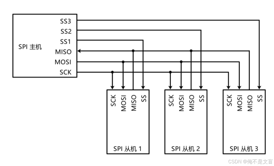
SPI主要由四條信號線組成,分別是 SCK、MOSI、MISO 和 SS。
1、串行時鐘線(SCK)
- 功能:SCK 是由主設備產生的時鐘信號,用于同步主設備和從設備之間的數據傳輸。主設備通過控制 SCK 的頻率來決定數據傳輸的速率,每一個時鐘脈沖對應一位數據的傳輸。
- 工作原理:在時鐘信號的上升沿或下降沿,主設備和從設備會進行數據的發送和接收操作。具體是上升沿還是下降沿進行數據操作,取決于 SPI 的工作模式(由時鐘極性 CPOL 和時鐘相位 CPHA 決定)。
2、主輸出從輸入線(MOSI)
- 功能:MOSI用于主設備向從設備發送數據。。當主設備需要向從設備傳輸數據時,它會將數據通過 MOSI 線逐位發送出去,從設備在相應的時鐘信號控制下接收這些數據。
- 工作原理:在 SCK 的有效沿(上升沿或下降沿),主設備將待發送的數據位放到 MOSI 線上,從設備在同一時刻讀取該線上的數據位。這樣,隨著 SCK 時鐘信號的不斷變化,主設備就可以將數據依次發送給從設備。
3、主輸入從輸出線(MISO)
- 功能:MISO 用于從設備向主設備發送數據。當從設備需要將數據反饋給主設備時,它會將數據通過 MISO 線逐位發送出去,主設備在相應的時鐘信號控制下接收這些數據。
- 工作原理:與 MOSI 類似,在 SCK 的有效沿,從設備將待發送的數據位放到 MISO 線上,主設備在同一時刻讀取該線上的數據位。通過這種方式,從設備可以將數據傳輸給主設備。
4、從設備選擇線(SS)?
- 功能:SS 線用于主設備選擇要與之通信的從設備。SPI 支持一主多從的拓撲結構,主設備通過拉低特定從設備的 SS 線來選中該從設備,使其進入工作狀態,準備進行數據傳輸。
- 工作原理:在 SPI 通信中,每個從設備都有一個獨立的 SS 線,當主設備需要與某個從設備通信時,將該從設備的 SS 線拉低(通常為低電平有效),其他從設備的 SS 線保持高電平。被選中的從設備會響應主設備的時鐘信號和數據傳輸請求,而未被選中的從設備則處于空閑狀態,不參與數據傳輸。
二、SPI協議
SPI四種模式
時鐘極性(CPOL)定義了時鐘空閑狀態電平
- CPOL=0,SCK 信號在空閑狀態(即沒有數據傳輸時)保持低電平。在這種情況下,SCK 信號的有效沿為上升沿(從低電平到高電平的跳變),數據通常在上升沿被采樣。
- CPOL=1,SCK 信號在空閑狀態保持高電平。此時,SCK 信號的有效沿為下降沿(從高電平到低電平的跳變),數據通常在下降沿被采樣。
時鐘相位(CPHA)定義了數據的采集時間
- CPHA=0,在SCK的第一個跳變沿(上升沿或下降沿)進行數據采樣。
- CPHA=1,在SCK的第二個跳變沿(上升沿或下降沿)進行數據采樣。
表1 SPI四種工作模式
| 模式 | CPOL | CPHA | 描述 |
| mode0 | 0 | 0 |  |
| mode1 | 0 | 1 | 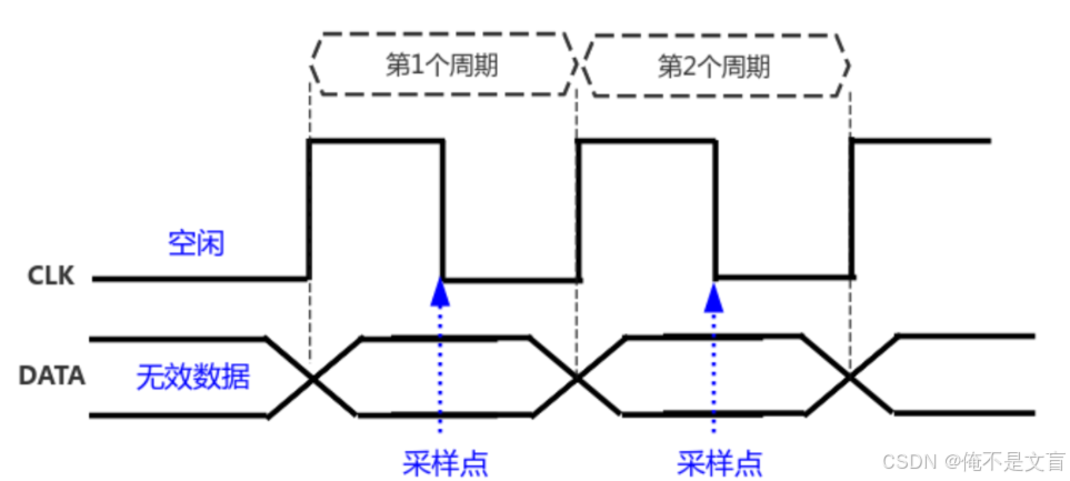 |
| mode2 | 1 | 0 | 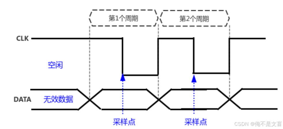 |
| mode3 | 1 | 1 | 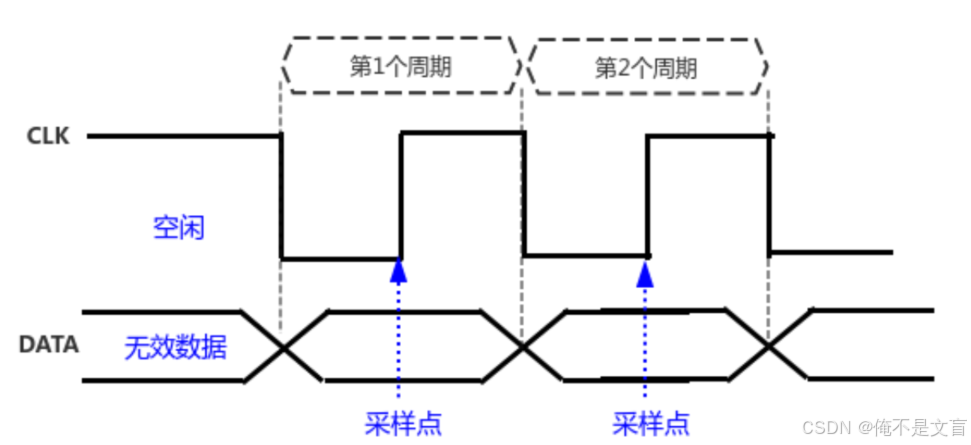 |
三、SPI總線設備驅動模型
1、平臺總線驅動模型
先來回顧一下平臺總線驅動模型。
平臺總線驅動模型將驅動程序分成兩部分:
一部分注冊一個platform_driver結構體;
另一部分注冊一個platform_device結構體
- 可以使用C文件注冊platform_device。
- 也可以使用設備樹創建一個節點,內核解析設備樹時注冊platform_device。
?
匹配機制概述?
在 Linux 內核中,platform_bus_type負責管理平臺設備(platform_device)和平臺驅動(platform_driver)的匹配過程。
platform_bus_type?定義了一個?match?函數,當有新的平臺設備或平臺驅動注冊到系統時,內核會調用這個?match?函數來判斷設備和驅動是否匹配。如果匹配成功,內核會調用驅動的?probe?函數來初始化設備。
platform_match源碼如下所示:
static int platform_match(struct device *dev, struct device_driver *drv)
{struct platform_device *pdev = to_platform_device(dev);struct platform_driver *pdrv = to_platform_driver(drv);/* When driver_override is set, only bind to the matching driver */if (pdev->driver_override)return !strcmp(pdev->driver_override, drv->name);/* Attempt an OF style match first */if (of_driver_match_device(dev, drv))return 1;/* Then try ACPI style match */if (acpi_driver_match_device(dev, drv))return 1;/* Then try to match against the id table */if (pdrv->id_table)return platform_match_id(pdrv->id_table, pdev) != NULL;/* fall-back to driver name match */return (strcmp(pdev->name, drv->name) == 0);
}
platform_match函數會按照以下順序來嘗試匹配設備和驅動:
- 檢查設備的driver_override字段;
- 嘗試使用設備樹(of)風格匹配;
- 嘗試使用ACPI風格匹配;
- 嘗試依據驅動的id_table進行匹配
- 若前面的匹配都失敗了,就使用設備和驅動的名稱進行匹配。
2、SPI數據結構
前面的硬件框架可以看出,SPI子系統涉及到2類硬件:SPI控制器、SPI設備。
在SPI總線設備驅動模型中,spi_master、spi_device和spi_driver是三個核心的數據結構和概念,它們共同協作實現對SPI設備的管理和驅動。
spi_master結構體
spi_master代表SPI主控制器,它是系統中負責管理SPI總線并與SPI從設備進行通信的硬件實體。在Linux內核中,它抽象魏一個spi_master結構體,用來描述和控制 SPI 主機控制器的各種屬性與操作,里面最重要的成員是transfer函數指針。?
struct spi_master {struct device	dev;struct list_head list;/* other than negative (== assign one dynamically), bus_num is fully* board-specific.  usually that simplifies to being SOC-specific.* example:  one SOC has three SPI controllers, numbered 0..2,* and one board's schematics might show it using SPI-2.  software* would normally use bus_num=2 for that controller.*/s16			bus_num;/* chipselects will be integral to many controllers; some others* might use board-specific GPIOs.*/u16			num_chipselect;/* some SPI controllers pose alignment requirements on DMAable* buffers; let protocol drivers know about these requirements.*/u16			dma_alignment;/* spi_device.mode flags understood by this controller driver */u16			mode_bits;/* bitmask of supported bits_per_word for transfers */u32			bits_per_word_mask;
#define SPI_BPW_MASK(bits) BIT((bits) - 1)
#define SPI_BIT_MASK(bits) (((bits) == 32) ? ~0U : (BIT(bits) - 1))
#define SPI_BPW_RANGE_MASK(min, max) (SPI_BIT_MASK(max) - SPI_BIT_MASK(min - 1))/* limits on transfer speed */u32			min_speed_hz;u32			max_speed_hz;/* other constraints relevant to this driver */u16			flags;
#define SPI_MASTER_HALF_DUPLEX	BIT(0)		/* can't do full duplex */
#define SPI_MASTER_NO_RX	BIT(1)		/* can't do buffer read */
#define SPI_MASTER_NO_TX	BIT(2)		/* can't do buffer write */
#define SPI_MASTER_MUST_RX      BIT(3)		/* requires rx */
#define SPI_MASTER_MUST_TX      BIT(4)		/* requires tx *//** on some hardware transfer / message size may be constrained* the limit may depend on device transfer settings*/size_t (*max_transfer_size)(struct spi_device *spi);size_t (*max_message_size)(struct spi_device *spi);/* I/O mutex */struct mutex		io_mutex;/* lock and mutex for SPI bus locking */spinlock_t		bus_lock_spinlock;struct mutex		bus_lock_mutex;/* flag indicating that the SPI bus is locked for exclusive use */bool			bus_lock_flag;/* Setup mode and clock, etc (spi driver may call many times).** IMPORTANT:  this may be called when transfers to another* device are active.  DO NOT UPDATE SHARED REGISTERS in ways* which could break those transfers.*/int			(*setup)(struct spi_device *spi);/* bidirectional bulk transfers** + The transfer() method may not sleep; its main role is*   just to add the message to the queue.* + For now there's no remove-from-queue operation, or*   any other request management* + To a given spi_device, message queueing is pure fifo** + The master's main job is to process its message queue,*   selecting a chip then transferring data* + If there are multiple spi_device children, the i/o queue*   arbitration algorithm is unspecified (round robin, fifo,*   priority, reservations, preemption, etc)** + Chipselect stays active during the entire message*   (unless modified by spi_transfer.cs_change != 0).* + The message transfers use clock and SPI mode parameters*   previously established by setup() for this device*/int			(*transfer)(struct spi_device *spi,struct spi_message *mesg);/* called on release() to free memory provided by spi_master */void			(*cleanup)(struct spi_device *spi);/** Used to enable core support for DMA handling, if can_dma()* exists and returns true then the transfer will be mapped* prior to transfer_one() being called.  The driver should* not modify or store xfer and dma_tx and dma_rx must be set* while the device is prepared.*/bool			(*can_dma)(struct spi_master *master,struct spi_device *spi,struct spi_transfer *xfer);/** These hooks are for drivers that want to use the generic* master transfer queueing mechanism. If these are used, the* transfer() function above must NOT be specified by the driver.* Over time we expect SPI drivers to be phased over to this API.*/bool				queued;struct kthread_worker		kworker;struct task_struct		*kworker_task;struct kthread_work		pump_messages;spinlock_t			queue_lock;struct list_head		queue;struct spi_message		*cur_msg;bool				idling;bool				busy;bool				running;bool				rt;bool				auto_runtime_pm;bool                            cur_msg_prepared;bool				cur_msg_mapped;struct completion               xfer_completion;size_t				max_dma_len;int (*prepare_transfer_hardware)(struct spi_master *master);int (*transfer_one_message)(struct spi_master *master,struct spi_message *mesg);int (*unprepare_transfer_hardware)(struct spi_master *master);int (*prepare_message)(struct spi_master *master,struct spi_message *message);int (*unprepare_message)(struct spi_master *master,struct spi_message *message);int (*spi_flash_read)(struct  spi_device *spi,struct spi_flash_read_message *msg);bool (*flash_read_supported)(struct spi_device *spi);/** These hooks are for drivers that use a generic implementation* of transfer_one_message() provied by the core.*/void (*set_cs)(struct spi_device *spi, bool enable);int (*transfer_one)(struct spi_master *master, struct spi_device *spi,struct spi_transfer *transfer);void (*handle_err)(struct spi_master *master,struct spi_message *message);/* gpio chip select */int			*cs_gpios;/* statistics */struct spi_statistics	statistics;/* DMA channels for use with core dmaengine helpers */struct dma_chan		*dma_tx;struct dma_chan		*dma_rx;/* dummy data for full duplex devices */void			*dummy_rx;void			*dummy_tx;int (*fw_translate_cs)(struct spi_master *master, unsigned cs);
};
spi_device結構體
spi_device代表一個具體的 SPI 從設備,它連接到 SPI 總線上,是 SPI 通信的目標設備。在 Linux 內核中,它抽象為一個spi_device結構體,用于描述 SPI 從設備的各種屬性。
struct spi_device {struct device		dev;struct spi_master	*master;u32			max_speed_hz;u8			chip_select;u8			bits_per_word;u16			mode;
#define	SPI_CPHA	0x01			/* clock phase */
#define	SPI_CPOL	0x02			/* clock polarity */
#define	SPI_MODE_0	(0|0)			/* (original MicroWire) */
#define	SPI_MODE_1	(0|SPI_CPHA)
#define	SPI_MODE_2	(SPI_CPOL|0)
#define	SPI_MODE_3	(SPI_CPOL|SPI_CPHA)
#define	SPI_CS_HIGH	0x04			/* chipselect active high? */
#define	SPI_LSB_FIRST	0x08			/* per-word bits-on-wire */
#define	SPI_3WIRE	0x10			/* SI/SO signals shared */
#define	SPI_LOOP	0x20			/* loopback mode */
#define	SPI_NO_CS	0x40			/* 1 dev/bus, no chipselect */
#define	SPI_READY	0x80			/* slave pulls low to pause */
#define	SPI_TX_DUAL	0x100			/* transmit with 2 wires */
#define	SPI_TX_QUAD	0x200			/* transmit with 4 wires */
#define	SPI_RX_DUAL	0x400			/* receive with 2 wires */
#define	SPI_RX_QUAD	0x800			/* receive with 4 wires */int			irq;void			*controller_state;void			*controller_data;char			modalias[SPI_NAME_SIZE];int			cs_gpio;	/* chip select gpio *//* the statistics */struct spi_statistics	statistics;/** likely need more hooks for more protocol options affecting how* the controller talks to each chip, like:*  - memory packing (12 bit samples into low bits, others zeroed)*  - priority*  - drop chipselect after each word*  - chipselect delays*  - ...*/
};
spi_driver結構體
spi_driver代表 SPI 設備的驅動程序,它實現了對 SPI 從設備的具體操作和功能。在 Linux 內核中,它抽象為一個spi_driver結構體,包含了驅動程序的各種回調函數。
struct spi_driver {const struct spi_device_id *id_table;int			(*probe)(struct spi_device *spi);int			(*remove)(struct spi_device *spi);void			(*shutdown)(struct spi_device *spi);struct device_driver	driver;
};
三者關系
spi_master負責管理 SPI 總線,為spi_device提供通信的基礎;spi_device代表具體的 SPI 從設備,通過spi_master注冊到系統中;spi_driver則負責驅動spi_device,通過與spi_device匹配后,實現對設備的具體操作和數據傳輸。它們共同構成了 Linux 內核中 SPI 總線設備驅動模型的核心部分。
3、SPI驅動框架
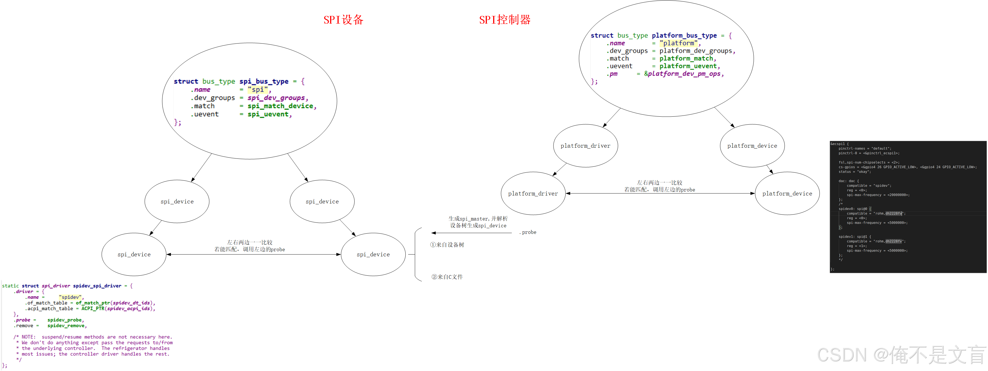
在 Linux 系統中,SPI 控制器通常是通過平臺總線驅動模型進行創建和管理的,而 SPI 設備則是基于 SPI 總線驅動模型來創建和操作的。


)

之安裝master節點組件(kube-apiserver))


)


)


