????🔎【博主簡介】🔎
????????🏅CSDN博客專家
????????🏅2021年博客之星物聯網與嵌入式開發TOP5
????????🏅2022年博客之星物聯網與嵌入式開發TOP4
????????🏅2021年2022年C站百大博主
????????🏅華為云開發者社區專家博主
????????🏅阿里云開發者社區專家博主
????????🏅掘金INFOQ騰訊云優秀博主📝《個人主頁》謓澤-CSDN博客
🥰《個人社區》QRS社區-CSDN社區云
👀《系列專欄》STM32-單片機
📣 點贊👍+ 收藏??+ 留言💬
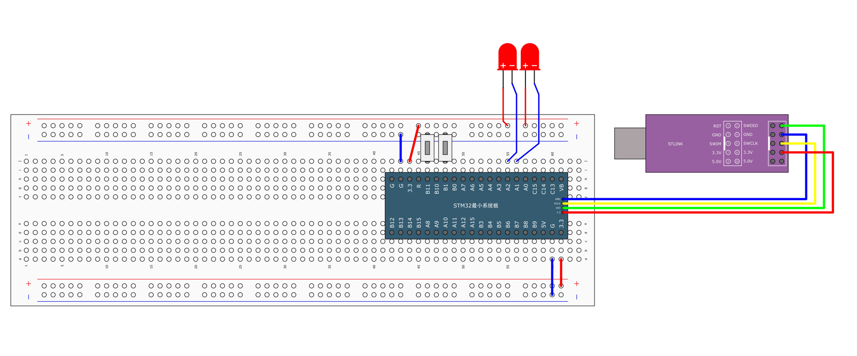
⒈按鍵控制LED燈
概述?在五一單片機當中博主也有寫過一篇關于輕觸按鍵控制的文章,對輕觸按鍵不了解的話可以看看🔗【51單片機】獨立按鍵控制LED燈(四種形式)
說明?在下述圖當中是兩個按鍵控制兩個LED燈的面包板接線圖。
說明?博主并非使用面包板接線圖的,而是自己使用了洞洞板來焊接一個個模塊,最終合成一個開發板的。就像和普中51的A2開發板一樣。
示例要求如下👇
- 按下B1按鍵第一個LED點亮,再按一下B1按鍵LED燈熄滅。依次...
- 按下B11按鍵第二個LED點亮,再按一下B11按鍵LED燈熄滅。依次...
🎓拓展知識點如下?
- 快捷鍵[CTRL+ALT+空格]可以彈出代碼提示框。?
- 當我們把GPIO初始化配置好了之后單片機默認是低電平,所以我們需要再初始化完成之后再設置成高電平。
- 按鍵當中的初始化使用的Mode模式是上拉模式的。注:當然你也可以自己在外部電路上接一個上拉電阻,這樣模式的選擇也可以不用是上拉模式。
注意?按鍵會產生抖動,一般有兩種方法可以解決按鍵產生抖動的問題。
⒈軟件消抖、定時器掃描或延時函數。
⒉硬件消抖、小電容103并聯接地。
第一個程序代碼
示例代碼如下?
main.c
#include "stm32f10x.h"                  // Device header
#include "Delay.h"
#include "LED.h"
#include "Key.h"
#include "stdint.h"
uint8_t Ret;int main(void)
{LED_Init();Key_Init();while (1){Ret=KeyNum();if(Ret==1){	LED1_Ture();}else if(Ret==2){LED2_Ture();}else{LED3_Ture();}}
}
LED.c
#include "stm32f10x.h"                  // Device header/*
概述:LED的初始化函數。
㈠使用RCC開啟GPIO的時鐘 [RCC-即復位與時鐘控制,主要是通過寄存器配置時鐘源]㈡使用GPIO_Init函數初始化GPIO口。㈢使用輸出或者輸入函數控制GPIO口。
說明:快捷鍵[CTRL+ALT+空格]可以彈出代碼提示框。
*/
void LED_Init()
{RCC_APB2PeriphClockCmd(RCC_APB2Periph_GPIOA|RCC_APB2Periph_GPIOC, ENABLE);GPIO_InitTypeDef GPIO_InitStructure;GPIO_InitStructure.GPIO_Mode = GPIO_Mode_Out_PP;GPIO_InitStructure.GPIO_Pin = GPIO_Pin_0 | GPIO_Pin_15 | GPIO_Pin_14;GPIO_InitStructure.GPIO_Speed = GPIO_Speed_50MHz;GPIO_Init(GPIOA, &GPIO_InitStructure);GPIO_Init(GPIOC, &GPIO_InitStructure);GPIO_SetBits(GPIOA, GPIO_Pin_0);//GPIO_Pin_x為高電平GPIO_SetBits(GPIOC, GPIO_Pin_15 | GPIO_Pin_14);             //GPIO_Pin_x為高電平
}
//ON:打開 OFF:關閉
void LED1_ON()
{GPIO_SetBits(GPIOA,GPIO_Pin_1);
}void LED1_OFF()
{GPIO_ResetBits(GPIOA,GPIO_Pin_1);
}void LED2_ON()
{GPIO_SetBits(GPIOC,GPIO_Pin_15);
}void LED2_OFF()
{GPIO_ResetBits(GPIOC,GPIO_Pin_15);
}
//IO電平翻轉
void LED1_Ture()
{if(GPIO_ReadOutputDataBit(GPIOA, GPIO_Pin_0) == 0){//如果PA0的輸出寄存器=0GPIO_SetBits(GPIOA, GPIO_Pin_0);//PA1=1}else//如果PA0的輸出寄存器=1{GPIO_ResetBits(GPIOA,GPIO_Pin_0);//PA1=0}
}void LED2_Ture()
{if(GPIO_ReadOutputDataBit(GPIOC, GPIO_Pin_15) == 0){GPIO_SetBits(GPIOC, GPIO_Pin_15);}else{GPIO_ResetBits(GPIOC,GPIO_Pin_15);}
}void LED3_Ture()
{if(GPIO_ReadOutputDataBit(GPIOC, GPIO_Pin_14) == 0){GPIO_SetBits(GPIOC, GPIO_Pin_14);}else{GPIO_ResetBits(GPIOC,GPIO_Pin_14);}
}
LED.h
#ifndef __LED_H
#define __LED_Hextern void LED_Init(void);extern void LED1_ON(void);
extern void LED1_OFF(void);
extern void LED2_ON(void);
extern void LED2_OFF(void);extern void LED1_Ture(void);
extern void LED2_Ture(void);
extern void LED3_Ture(void);
#endif
Key.c
#include "stm32f10x.h"                  // Device header
#include "Delay.h"void Key_Init(void)
{RCC_APB2PeriphClockCmd(RCC_APB2Periph_GPIOB, ENABLE);GPIO_InitTypeDef GPIO_InitStructure;GPIO_InitStructure.GPIO_Mode = GPIO_Mode_IPU;GPIO_InitStructure.GPIO_Pin = GPIO_Pin_1 | GPIO_Pin_11;GPIO_InitStructure.GPIO_Speed = GPIO_Speed_50MHz;GPIO_Init(GPIOB, &GPIO_InitStructure);
}uint8_t Key_GetNum(void)
{uint8_t KeyNum = 0;if (GPIO_ReadInputDataBit(GPIOB, GPIO_Pin_1) == 0){Delay_ms(20);while (GPIO_ReadInputDataBit(GPIOB, GPIO_Pin_1) == 0);Delay_ms(20);KeyNum = 1;}if (GPIO_ReadInputDataBit(GPIOB, GPIO_Pin_11) == 0){Delay_ms(20);while (GPIO_ReadInputDataBit(GPIOB, GPIO_Pin_11) == 0);Delay_ms(20);KeyNum = 2;}return KeyNum;
}
Key.h
#ifndef __Key_H
#define __Key_Hextern void Key_Init(void);
extern unsigned char KeyNum(void);#endif
說明?以上便是獨立按鍵控制LED的全部代碼。
注意?在這里對應的按鍵是可以控制對應LED燈的以及翻轉狀態,當按鍵按下的時候對應的LED燈點亮、當按鍵松手的時候對應的LED燈熄滅。
//大多數運用場景在IO口電平翻轉
GPIO_ReadOutputDataBit(GPIOA, GPIO_Pin_0)
⒉光敏傳感器控制蜂鳴器
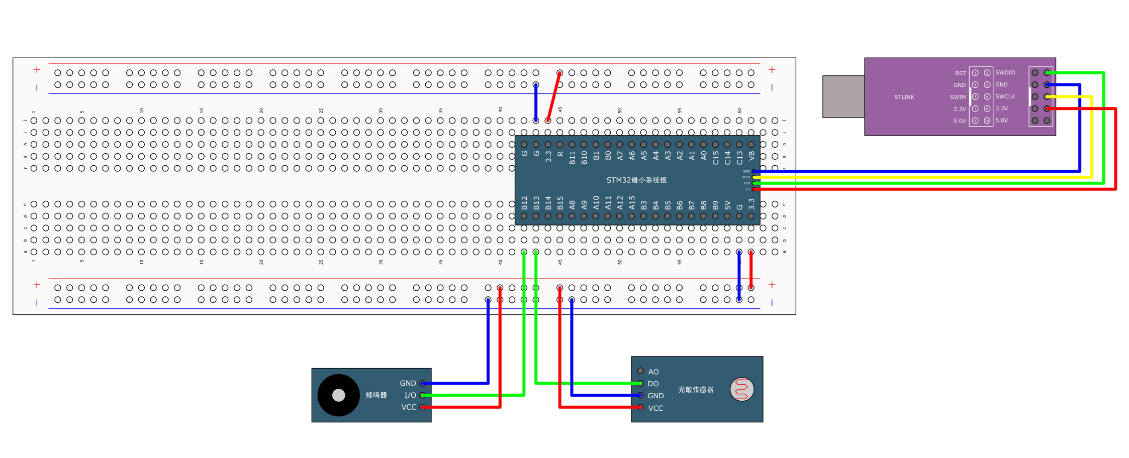
概述?第二個示例講的是用光敏電阻傳感器控制蜂鳴器。如果你對蜂鳴器不是很理解的話,推薦看看博主寫的這篇文章。🔗
說明?在下述圖當中是兩個按鍵控制兩個LED燈的面包板接線圖。
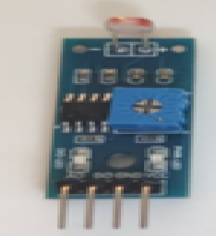
重要知識點?在這里還是主要介紹下光敏傳感器到底是啥玩意。
說明?在上述主要是由光敏電阻、電位器、電阻、LED燈、LM393組合而成的光敏傳感器的模塊,其主要功能是?光線越強,光敏電阻的阻值就會越小,信號輸出低電平(燈亮),當遮擋光敏電阻的時候,信號輸出為高電平(燈滅)
引腳?分別有四個引腳,1.Vcc、2.Gnd、3.AO、4.DO?
注意?AO是ADC模數轉換的引腳。
檢測距離調節:順時針調節電位器,檢測距離增加;逆時針調節電位器,檢測距離減少。
第二個程序代碼
示例代碼如下?
main.h
#include "stm32f10x.h"                  // Device header
#include "Delay.h"
#include "Buzzer.h"
#include "LightSensor.h"int main(void)
{Buzzer_Init();LightSensor_Init();while (1){if (LightSensor_Get() == 1){Buzzer_ON();}else{Buzzer_OFF();}}
}
Key.c
#include "stm32f10x.h"                  // Device header
#include "Delay.h"void Key_Init(void)
{RCC_APB2PeriphClockCmd(RCC_APB2Periph_GPIOB, ENABLE);GPIO_InitTypeDef GPIO_InitStructure;GPIO_InitStructure.GPIO_Mode = GPIO_Mode_IPU;GPIO_InitStructure.GPIO_Pin = GPIO_Pin_1 | GPIO_Pin_11;GPIO_InitStructure.GPIO_Speed = GPIO_Speed_50MHz;GPIO_Init(GPIOB, &GPIO_InitStructure);
}uint8_t Key_GetNum(void)
{uint8_t KeyNum = 0;if (GPIO_ReadInputDataBit(GPIOB, GPIO_Pin_1) == 0){Delay_ms(20);while (GPIO_ReadInputDataBit(GPIOB, GPIO_Pin_1) == 0);Delay_ms(20);KeyNum = 1;}if (GPIO_ReadInputDataBit(GPIOB, GPIO_Pin_11) == 0){Delay_ms(20);while (GPIO_ReadInputDataBit(GPIOB, GPIO_Pin_11) == 0);Delay_ms(20);KeyNum = 2;}return KeyNum;
}
Key.h
#ifndef __KEY_H
#define __KEY_Hvoid Key_Init(void);
uint8_t Key_GetNum(void);#endif
Buzzer.c
#include "stm32f10x.h"                  // Device headervoid Buzzer_Init(void)
{RCC_APB2PeriphClockCmd(RCC_APB2Periph_GPIOB, ENABLE);GPIO_InitTypeDef GPIO_InitStructure;GPIO_InitStructure.GPIO_Mode = GPIO_Mode_Out_PP;GPIO_InitStructure.GPIO_Pin = GPIO_Pin_12;GPIO_InitStructure.GPIO_Speed = GPIO_Speed_50MHz;GPIO_Init(GPIOB, &GPIO_InitStructure);GPIO_SetBits(GPIOB, GPIO_Pin_12);
}void Buzzer_ON(void)
{GPIO_ResetBits(GPIOB, GPIO_Pin_12);
}void Buzzer_OFF(void)
{GPIO_SetBits(GPIOB, GPIO_Pin_12);
}void Buzzer_Turn(void)
{if (GPIO_ReadOutputDataBit(GPIOB, GPIO_Pin_12) == 0){GPIO_SetBits(GPIOB, GPIO_Pin_12);}else{GPIO_ResetBits(GPIOB, GPIO_Pin_12);}
}
Buzzer.h
#ifndef __BUZZER_H
#define __BUZZER_Hvoid Buzzer_Init(void);
void Buzzer_ON(void);
void Buzzer_OFF(void);
void Buzzer_Turn(void);#endif
LightSensor.c
#include "stm32f10x.h"                  // Device headervoid LightSensor_Init(void)
{RCC_APB2PeriphClockCmd(RCC_APB2Periph_GPIOB, ENABLE);GPIO_InitTypeDef GPIO_InitStructure;GPIO_InitStructure.GPIO_Mode = GPIO_Mode_IPU;GPIO_InitStructure.GPIO_Pin = GPIO_Pin_13;GPIO_InitStructure.GPIO_Speed = GPIO_Speed_50MHz;GPIO_Init(GPIOB, &GPIO_InitStructure);
}uint8_t LightSensor_Get(void)
{return GPIO_ReadInputDataBit(GPIOB, GPIO_Pin_13);
}
LightSensor.h
#ifndef __LIGHT_SENSOR_H
#define __LIGHT_SENSOR_Hvoid LightSensor_Init(void);
uint8_t LightSensor_Get(void);#endif
說明?以上便是第二個示例代碼的全部程序內容。
【STM32】按鍵控制LED 光敏傳感器控制蜂鳴器

本文來自互聯網用戶投稿,該文觀點僅代表作者本人,不代表本站立場。本站僅提供信息存儲空間服務,不擁有所有權,不承擔相關法律責任。 如若轉載,請注明出處:http://www.pswp.cn/news/907341.shtml 繁體地址,請注明出處:http://hk.pswp.cn/news/907341.shtml 英文地址,請注明出處:http://en.pswp.cn/news/907341.shtml
如若內容造成侵權/違法違規/事實不符,請聯系多彩編程網進行投訴反饋email:809451989@qq.com,一經查實,立即刪除!相關文章
Java/python/JavaScript/C/C++/GO最佳實現)
華為OD機試真題——斗地主之順子(2025B卷:100分)Java/python/JavaScript/C/C++/GO最佳實現
2025 B卷 100分 題型 本專欄內全部題目均提供Java、python、JavaScript、C、C++、GO六種語言的最佳實現方式; 并且每種語言均涵蓋詳細的問題分析、解題思路、代碼實現、代碼詳解、3個測試用例以及綜合分析; 本文收錄于專欄:《2025華為OD真題目錄+全流程解析+備考攻略+經驗分…

Qt找不到windows API報錯:error: LNK2019: 無法解析的外部符號 __imp_OpenClipboard
筆者在開發中出現的bug完整報錯如下:
spcm_ostools_win.obj:-1: error: LNK2019: 無法解析的外部符號 __imp_OpenClipboard,函數 "void __cdecl spcmdrv::vCopyToClipboard(char const *,unsigned __int64)" (?vCopyToClipboardspcmdrvYAXPE…

4.8.4 利用Spark SQL實現分組排行榜
在本次實戰中,我們的目標是利用Spark SQL實現分組排行榜,特別是計算每個學生分數最高的前3個成績。任務的原始數據由一組學生成績組成,每個學生可能有多個成績記錄。我們首先將這些數據讀入Spark DataFrame,然后按學生姓名分組&am…
![[PyMySQL]](http://pic.xiahunao.cn/[PyMySQL])

cs224w課程學習筆記-第12課
cs224w課程學習筆記-第12課 知識圖譜問答 前言一、問答類型分類二、路徑查詢(Path queries)2.1 直觀查詢方法2.2 TransE 擴展2.3 TransE 能力分析 三、連詞查詢(conjunctive queries)3.1 Query2box 原理1)、投影2)、交集查詢(AND 操作)3)、聯合查詢(OR 操…

AI任務相關解決方案2-基于WOA-CNN-BIGRU-Transformer模型解決光纖通信中的非線性問題
文章目錄 1. 項目背景與研究意義1.1 光纖通信中的非線性問題1.2 神經網絡在光纖非線性補償中的應用現狀 2. 現有模型 CNN-BIGRU-attention 分析2.1 模型架構與工作原理2.2 模型性能評估與局限性 3. 新模型優化方案3.1 WOA算法原理與優勢3.2 WOA-CNN-BIGRU-MHA模型構建3.3 WOA-C…

HTTP Accept簡介
一、HTTP Accept是什么
HTTP協議是一個客戶端和服務器之間進行通信的標準協議,它定義了發送請求和響應的格式。而HTTP Accept是HTTP協議中的一個HTTP頭部,用于告訴服務器請求方所期望的響應格式。這些格式可以是媒體類型、字符集、語言等信息。
HTTP A…
)
39-居住證管理系統(小程序)
技術棧: springBootVueMysqlUni-app
功能點: 群眾端 警方端 管理員端 群眾端:
1.首頁: 輪播圖展示、公告信息列表
2.公告欄: 公告查看及評論
3.我的:
聯系我們: 可在線咨詢管理員問題 實時回復
居住證登記申請
回執單查看
領證信息查看
4.個人中心: 個人信息查看及修改…

鴻蒙OSUniApp 開發的滑動圖片墻組件#三方框架 #Uniapp
UniApp 開發的滑動圖片墻組件
前言
在移動應用中,圖片墻是一種極具視覺沖擊力的內容展示方式,廣泛應用于相冊、商品展示、社交分享等場景。一個優秀的滑動圖片墻組件不僅要支持流暢的滑動瀏覽,還要兼容不同設備的分辨率和性能,尤…

碰一碰系統源碼搭建==saas系統
搭建“碰一碰”系統(通常指基于NFC或藍牙的短距離交互功能)的源碼實現,需結合具體技術棧和功能需求。以下是關鍵步驟和示例代碼: 技術選型
NFC模式:適用于Android/iOS設備的近場通信,需處理NDEF協議。藍牙…

自動駕駛決策規劃框架詳解:從理論到實踐
歡迎來到《自動駕駛決策規劃框架詳解:從理論到實踐》的第二章。在本章中,我們將深入探討自動駕駛系統中至關重要的“大腦”——決策規劃模塊。我們將從基本概念入手,逐步解析主流的決策規劃框架,包括經典的路徑速度解耦方法、工業界廣泛應用的Apollo Planning框架、應對復雜…

服務器定時任務查看和編輯
在 Ubuntu 系統中,查看當前系統中已開啟的定時任務主要有以下幾種方式,分別針對不同類型的定時任務管理方式(如 crontab、systemd timer 等):
查看服務器定時任務
一、查看用戶級別的 Crontab 任務
每個用戶都可以配…

小白的進階之路系列之四----人工智能從初步到精通pytorch自定義數據集下
本篇涵蓋的內容
在之前的文章中,我們已經討論了如何獲取數據,轉換數據以及如何準備自定義數據集,本篇文章將涵蓋更加深入的問題,希望通過詳細的代碼示例,幫助大家了解PyTorch自定義數據集是如何應對各種復雜實際情況中,數據處理的。
更加詳細的,我們將討論下面一些內容…

DeepSeek實戰:打造智能數據分析與可視化系統
DeepSeek實戰:打造智能數據分析與可視化系統
1. 數據智能時代:DeepSeek數據分析系統入門
在數據驅動的決策時代,智能數據分析系統正成為企業核心競爭力。本節將使用DeepSeek構建一個從數據清洗到可視化分析的全流程智能系統。
1.1 系統核心功能架構
class DataAnalysisS…

力扣100題---字母異位詞分組
1.字母異位詞分組 給你一個字符串數組,請你將 字母異位詞 組合在一起。可以按任意順序返回結果列表。 字母異位詞 是由重新排列源單詞的所有字母得到的一個新單詞。 方法一:字母排序 class Solution {public List<List<String>> groupAnagr…

使用子查詢在 SQL Server 中進行數據操作
在 SQL Server 中,子查詢(Subquery)是一種在查詢中嵌套另一個查詢的技術,可以用來執行復雜的查詢、過濾數據或進行數據計算。子查詢通常被用在 SELECT、INSERT、UPDATE 或 DELETE 語句中,可以幫助我們高效地解決問題。…

Flask集成pyotp生成動態口令
Python中的pyotp模塊是一個用于生成和驗證一次性密碼(OTP)的庫,支持基于時間(TOTP)和計數器(HOTP)的兩種主流算法。它遵循RFC 4226(HOTP)和RFC 6238(TOTP&…

觸控精靈 ADB運行模式填寫電腦端IP教程
?ADB模式,如果你手機已經root則可以直接運行,無需安裝電腦端。
?ADB模式,如果你手機沒有root,那你可以windows電腦下載【極限投屏】軟件,然后你的手機和電腦的網絡要同一個wifi,然后把你電腦的ip地址填寫…

【Python】 -- 趣味代碼 - 佩奇
文章目錄 文章目錄 00 佩奇程序設計框架1. 繪圖設置2. 繪制卡通人物的各個部分3. 主程序總結01 佩奇程序設計00 佩奇程序設計框架
這段代碼使用 turtle 模塊繪制了一個粉色的卡通人物圖像,主要功能包括繪制鼻子、頭、耳朵、眼睛、腮、嘴、身體、手、腳和尾巴等部分。代碼的主…
)
uniapp-商城-69-shop(2-商品列表,點擊商品展示,商品的詳情, vuex的使用,rich-text使用)
頁面中將我們的數據進行了羅列,對于單個數據的展示,還需要進行開發,這里使用了點擊商品后,進行彈窗展示。 同樣這里用一個組件來進行實現該彈窗的展示。 本文介紹了商品詳情彈窗的實現方案。主要采用Vuex進行狀態管理,通過幾個關鍵組件協同工作: 商品列表組件productItem…