一,MPU6500功能介紹
1.簡介
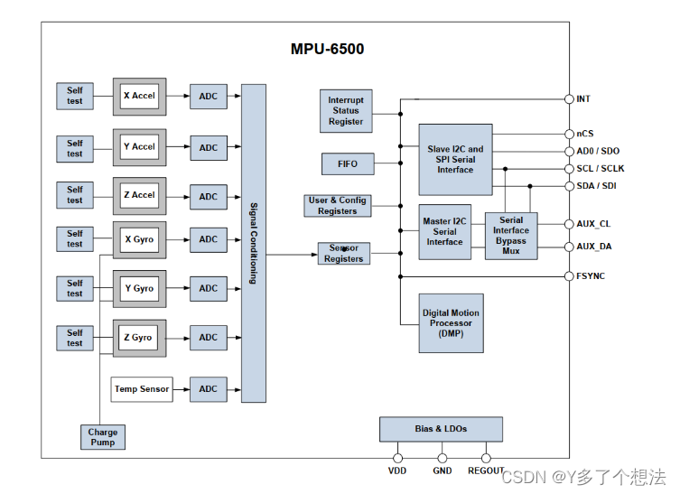
MPU6500是一款由TDK生產的運動/慣性傳感器,屬于慣性測量設備(IMU)的一種。MPU6500集成了3軸加速度計、3軸陀螺儀和一個板載數字運動處理器(DMP),能夠提供6軸的運動數據。這些數據包括加速度和角速度,分別對應于x, y, z軸。
MPU6500的接口類型包括I2C和SPI,支持數字輸出。它可以通過I2C或SPI接口與單片機或其他電子設備進行通信,以獲取設備的狀態和數據。此外,MPU6500還支持SPI通信模式,這使得其在某些應用中更為靈活。
2.性能與應用
性能方面,MPU6500具有較高的功耗效率和較小的封裝尺寸,實現了業內領先的消費類陀螺儀性能。它還在加速計噪聲、偏置和靈敏度方面進行了重大改進,進一步提升了其實用性和可靠性。
MPU6500被廣泛應用于多種應用程序中,如飛控系統、機器人、可穿戴設備等,特別是在需要高精度運動數據的場合。例如,有報道提到,大疆精靈3的飛控IMU就是采用了InvenSense的MPU6500芯片,顯示出其在實際應用中的廣泛適用性和良好性能。
總的來說,MPU6500是一款功能強大且性價比高的MEMS運動跟蹤設備,適用于各種需要精確運動數據的應用場景。
二,dts配置
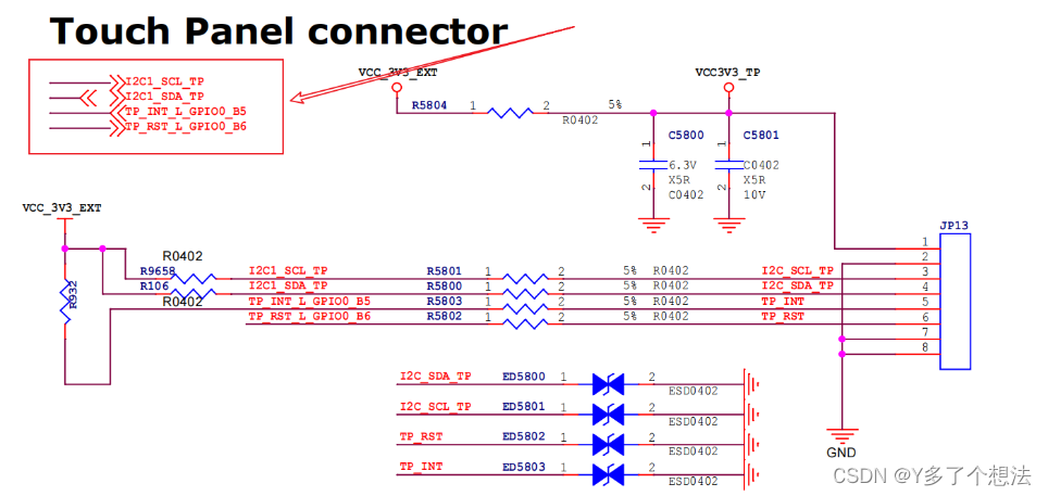
pmu6500通過I2C與CPU連接,使用I2C觸摸的接口(VCC,GND,SCL,SDA,INT)。
&i2c1 {status = "okay";mpu6500_acc: mpu_acc@68 {compatible = "mpu6500_acc";// 與mpu6500_acc.c定義匹配reg = <0x68>;irq-gpio = <&gpio0 RK_PB5 IRQ_TYPE_EDGE_RISING>;//中斷腳irq_enable = <0>;poll_delay_ms = <30>;type = <SENSOR_TYPE_ACCEL>;//傳感器類型layout = <5>;};mpu6500_gyro: mpu_gyro@68 {compatible = "mpu6500_gyro";//與mpu6500_gyro.c定義匹配reg = <0x68>;poll_delay_ms = <30>;type = <SENSOR_TYPE_GYROSCOPE>;//傳感器類型layout = <5>;};
};
三,驅動文件配置
1.源程序
kernel/drivers/input/sensors/accel/mpu6500_acc.c
kernel/drivers/input/sensors/gyro/mpu6500_gyro.c
mpu6500_acc.c是g-sensor驅動用來系統轉屏,另外一個mpu6500_gyro.c是陀螺儀驅動。
2.內核中加載驅動
CONFIG_MPU6500_ACC=y
CONFIG_GYRO_MPU6500=y
3.內核日志信息
編譯內核燒錄鏡可看到以下打印日志,則說明驅動加載成功并識別到設備。
rk3568:/ # dmesg | grep mpu6500
[    2.792117] gsensor_mpu6500 1-0068: sensor_register_device: mpu6500_acc, id = 29
[    2.792143] i2c i2c-1: sensor_probe: mpu6500_acc,00000000271b25e0
[    2.792190] gsensor_mpu6500 1-0068: sensor_chip_init:mpu6500_acc:devid=0x0,ops=0x000000007868205c
[    2.988057] gsensor_mpu6500 1-0068: sensor_irq_init:use polling,delay=30 ms
[    2.988177] gsensor_mpu6500 1-0068: sensor_misc_device_register:miscdevice: mma8452_daemon
[    2.988188] gsensor_mpu6500 1-0068: sensor_probe:initialized ok,sensor name:mpu6500_acc,type:2,id=29\x0a
[    5.148660] gyro_mpu6500 1-0068-1: sensor_register_device: mpu6500_gyro, id = 58
[    5.148676] i2c i2c-1: sensor_probe: mpu6500_gyro,0000000057dfc117
[    5.148703] gyro_mpu6500 1-0068-1: sensor_chip_init:mpu6500_gyro:devid=0x0,ops=0x000000000c6bf3bd
[    5.231839] gyro_mpu6500 1-0068-1: sensor_irq_init:use polling,delay=30 ms
[    5.232065] gyro_mpu6500 1-0068-1: sensor_misc_device_register:miscdevice: gyrosensor
[    5.232090] gyro_mpu6500 1-0068-1: sensor_probe:initialized ok,sensor name:mpu6500_gyro,type:4,id=58\x0a
[   26.143380] gsensor_mpu6500 1-0068: set sensor poll time to 66ms
[   26.227813] gsensor_mpu6500 1-0068: sensor on: starting poll sensor data 62ms
四,系統配置
1.Android 中的 sensor 相關宏配置
需要修改Android編譯設備配置,添加加速度計和陀螺儀的支持。
BoardConfig.mk中:
BOARD_GRAVITY_SENSOR_SUPPORT := true
BOARD_COMPASS_SENSOR_SUPPORT := false
BOARD_GYROSCOPE_SENSOR_SUPPORT := true
BOARD_PROXIMITY_SENSOR_SUPPORT := false
BOARD_LIGHT_SENSOR_SUPPORT := false
BOARD_PRESSURE_SENSOR_SUPPORT := false
BOARD_TEMPERATURE_SENSOR_SUPPORT := false
BOARD_USB_HOST_SUPPORT := true
支持哪些類型的 sensor,如果沒有,要配置成 false,否則 vts 和 cts 測試會失敗。
2.啟用自動旋轉功能,加速度計旋轉功能
frameworks/base/core/res/res/values/config.xml:
<bool name="config_supportAutoRotation">true</bool>frameworks/base/packages/SettingsProvider/res/values/defaults.xml:
<bool name="def_accelerometer_rotation">true</bool>
3.編譯燒錄
編譯固件燒錄后,正常情況下MPU-6500已經調試完成,進入系統打開設置--顯示--自動旋轉屏幕,此時轉動陀螺儀,系統方向會跟隨陀螺儀的方向轉動。
加速度和陀螺儀測試:
使用Sensor Sense軟件來測試傳感器的數據:
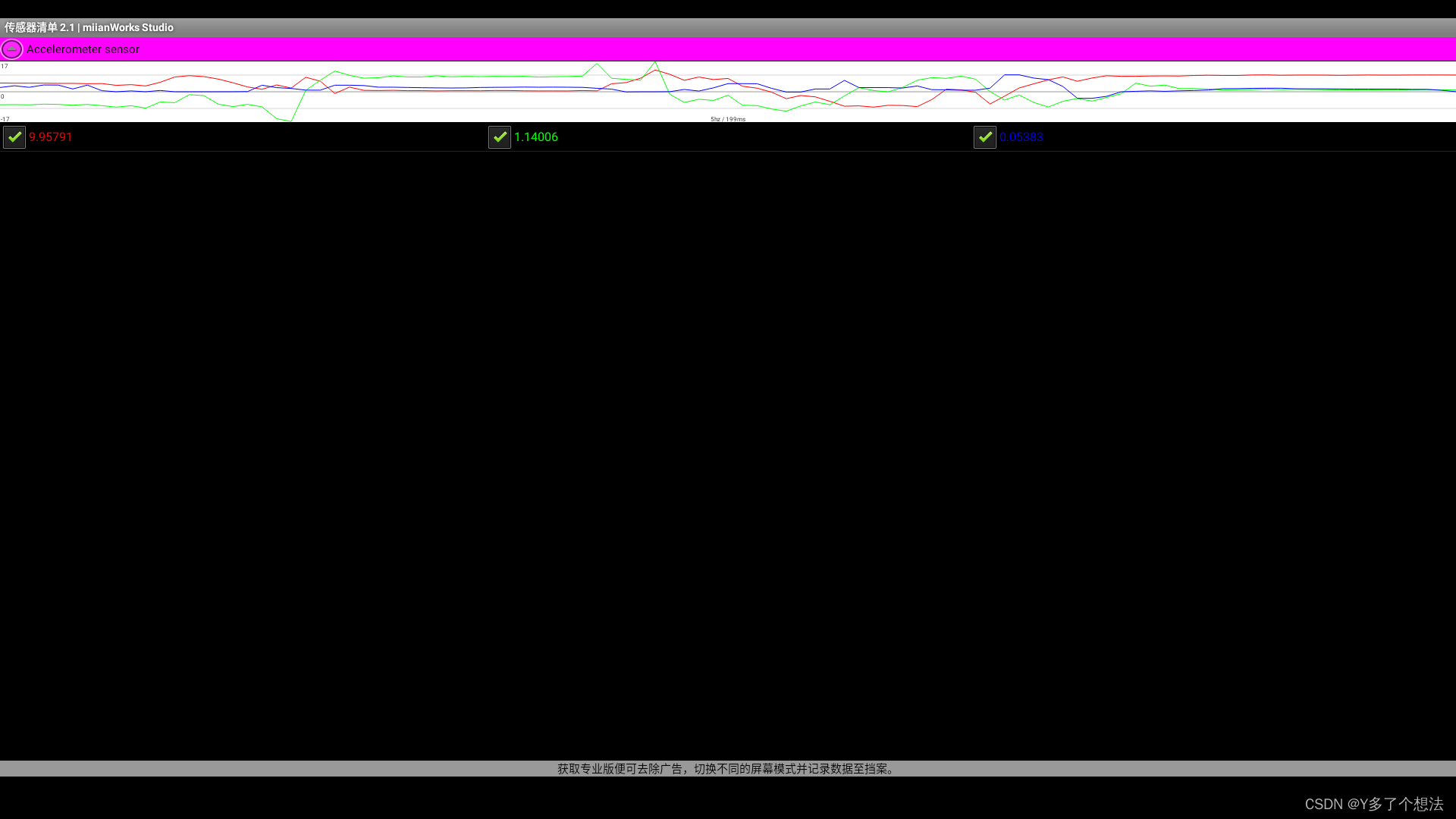
重力變化測試,翻轉傳感器模塊,可看到重力曲線隨之變化。
五,調試
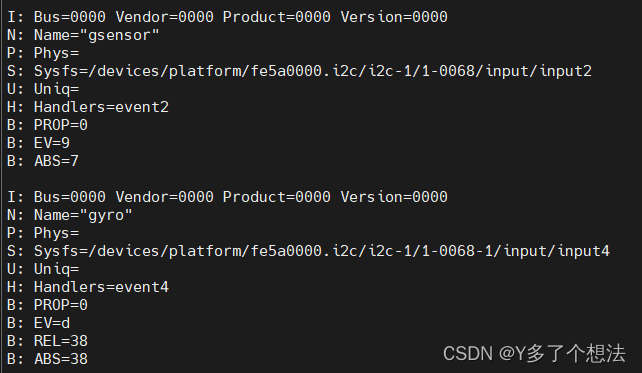
1.查看input設備
cat /proc/bus/input/devices
2.Gsensor 和 gyro 的校準
命令行校準方法,保持機器水平靜止放置,輸入以下命令校準:
#Gsensor
echo 1 > /sys/class/sensor_class/accel_calibration
#GYRO
echo 1 > /sys/class/sensor_class/gyro_calibration
查看校準值:
cat /sys/class/sensor_class/accel_calibration
cat /sys/class/sensor_class/gyro_calibration
如果無法查看校準值,則說明校準失敗,可以打印 kernel log 確定失敗原因。校準成功后,校準的值會保存到 nand 或 emmc 的 vendor storage 里面,不會被擦除,開機自動生效。
六,遇到的問題
1.方向不對
理論上x,y,z 3個軸的數據都在± 9.8之間變化。機器完全平放的狀態x,y軸接近0,z軸接近9.8。
如果發現方向不對,可以在驅動文件mpu6500_acc.c中交換x,y,z 3個軸的數據。
static int gsensor_report_value(struct i2c_client *client, struct sensor_axis *axis)
{struct sensor_private_data *sensor =(struct sensor_private_data *) i2c_get_clientdata(client);if (sensor->status_cur == SENSOR_ON) {/* Report acceleration sensor information */input_report_abs(sensor->input_dev, ABS_X, axis->x);input_report_abs(sensor->input_dev, ABS_Y, axis->y);input_report_abs(sensor->input_dev, ABS_Z, axis->z);input_sync(sensor->input_dev);}return 0;}
- 這段代碼是一個函數gyro_report_value,用于向輸入子系統報告陀螺儀(gyroscope)傳感器的數值。
函數接受兩個參數:一個是指向i2c_client結構的指針client,另一個是指向sensor_axis結構的指針axis,sensor_axis結構可能包含了三軸的數值(x、y、z)。
函數通過i2c_get_clientdata(client)獲取與i2c_client結構相關聯的私有數據結構sensor_private_data的指針sensor。
函數檢查sensor結構中的status_cur字段是否等于SENSOR_ON。如果當前傳感器狀態為開啟狀態,就會執行以下操作:
a. 使用input_report_rel函數向輸入設備報告陀螺儀的x軸數值,并將其存儲在ABS_RX中。
b. 使用input_report_rel函數向輸入設備報告陀螺儀的y軸數值,并將其存儲在ABS_RY中。
c. 使用input_report_rel函數向輸入設備報告陀螺儀的z軸數值,并將其存儲在ABS_RZ中。
最后,調用input_sync函數將所有報告的輸入事件同步到輸入設備。
- 例如要將X軸和Z軸數據對換后再進行input上報,可以在調用input_report_rel函數之前交換axis->x和axis->z的值。
static int gyro_report_value(struct i2c_client *client, struct sensor_axis *axis)
{struct sensor_private_data *sensor = (struct sensor_private_data *)i2c_get_clientdata(client);if (sensor->status_cur == SENSOR_ON) {/* Swap X and Z axis values */int temp = axis->x;axis->x = axis->z;axis->z = temp;/* Report gyro sensor information with swapped X and Z axis values */input_report_rel(sensor->input_dev, ABS_RX, axis->x);input_report_rel(sensor->input_dev, ABS_RY, axis->y);input_report_rel(sensor->input_dev, ABS_RZ, axis->z);input_sync(sensor->input_dev);}return 0;
}
這樣就實現了將X軸和Z軸數據對換后再進行input上報的功能。
2.luncher主界面不旋轉
在luncher主界面下不能旋轉,但在其他應用中可以旋轉(比如“資源管理器”“設置”“計算器”)。
可參考如下修改:
$SDK/frameworks/base# git diff
diff --git a/core/res/res/values/config.xml b/core/res/res/values/config.xml
index 970e63b11f37..398e1ea3c6df 100644
--- a/core/res/res/values/config.xml
+++ b/core/res/res/values/config.xml
@@ -570,7 +570,7 @@<!-- If true, the screen can be rotated via the accelerometer in all 4rotations as the default behavior. -->
-    <bool name="config_allowAllRotations">false</bool>
+    <bool name="config_allowAllRotations">true</bool><!-- If true, the direction rotation is applied to get to an application's requestedorientation is reversed.  Normally, the model is that landscape is


![[linux] matplotlib plt畫training dynamics指標曲線時,標記每個點的值](http://pic.xiahunao.cn/[linux] matplotlib plt畫training dynamics指標曲線時,標記每個點的值)


)

)
