本節書摘來自異步社區《CCIE路由和交換認證考試指南(第5版) (第1卷)》一書中的第1章,第1.6節虛擬交換系統,作者 【美】Narbik Kocharians(那比克 科查理安) , 【斯洛伐克】Peter Paluch(彼得 派拉奇),更多章節內容可以訪問云棲社區“異步社區”公眾號查看
1.6 虛擬交換系統
在所有現代網絡中,我們發現最重要的事情是創建一個能夠為設備、連接和服務,提供高可用性和高可靠性的拓撲。為了配置這些特性和功能,網絡工程師通常使用的方法是創建冗余的二層交換環境,比如使用冗余的一對或多條鏈路來提供多路徑。圖1-10展示了常見的交換網絡配置。
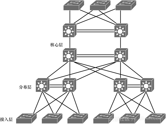
可以看出,這些冗余網絡設備和鏈路的應用和配置會快速提高網絡設計和操作的復雜性。有一個方法可以解決這種復雜性設計,就是部署虛擬交換系統。這項技術能夠實際地簡化網絡,因為它減少了網絡設備的數量,工程師無需再對冗余的交換機和鏈路進行復雜管理了。運行IOS-XE(在本章后文“IOS-XE”小節中詳細介紹)的Cisco Catalyst 6500和4500系列交換機能夠支持該特性。
在本節的討論中,我們使用VSS(虛擬交換系統)將一對Catalyst 4500或4500-X系列交換機合并到一臺網絡設備中。VSS管理冗余鏈路的方式,從外部設備看來,就像是管理單個Port-Channel。
這種部署方式簡化了網絡配置和操作,因為它不僅減少了三層路由鄰居的整體數量,同時還提供了無環的二層拓撲。
1.6.1 虛擬交換系統
想要部署VSS最基本的原因是想要將一對交換機在邏輯上合并到一臺網絡設備中,這一點之前已經提過了。為了更好地理解其中的過程,我們需要進一步查看這個特性為邏輯拓撲做哪些事情。舉例來說,位于網絡中分布層的VSS會與低于自己的接入層和高于自己的核心層進行通信,就好像它是一臺交換機,如圖1-11所示。
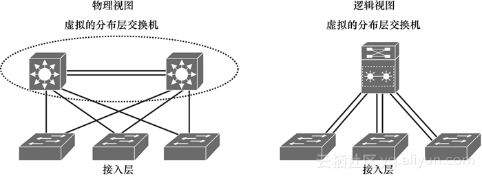
從圖1-11中可以看出,接入層的每臺交換機各自使用一個邏輯的Port-Channel連接了兩臺VSS交換機,因為對于外部設備來說,VSS看起來就是一臺單獨的交換機——或者說邏輯交換機。VSS設備也做出了相應的改進,比如它們可以在Port-Channel上管理冗余特性和負載均衡特性,以此來掌控鏈路的行為,即使它實際上連接了兩臺設備。雖然我們傾向于把VSS配置中的這些交換機看作是獨立的設備,但這么說并不準確。雖然這些交換機在物理上是相互分離的實體,但從操作和控制平面看來,它們實際上是一個單元。這種改進提供了無環的二層網絡拓撲。由于減少了網絡中路由對等體的數量,因此VSS也簡化了三層網絡拓撲,從而也將網絡的簡單化擴展到了數據平面中。
1.6.2 VSS主用和VSS備用交換機
前文中討論的更新,提到了VSS中每臺設備的操作,相關內容也可以延伸到“基于角色”的行為。在VSS的環境中,每臺獨立的交換機首先會為自己爭取到一個VSS進程中的特定工作角色,然后根據自己的角色作出相應行為。每一次工程師創建或重啟VSS時,對等體交換機之間都會協商各自的角色。最終結果就是一臺設備成為VSS主用(Active)交換機,另一臺設備成為VSS備用(Standby)交換機。
VSS主用交換機負責控制VSS,并在兩臺交換機上為交換模塊運行二層和三層控制協議。VSS主用交換機也為VSS提供管理功能,比如模塊的在線插拔(OIR)操作和接口的控制。
VSS主用和備用交換機在自己本地的接口上,為入向數據流量執行數據包轉發。但VSS備用交換機會把所有控制流量發送到VSS主用交換機,讓主用交換機進行 處理。
1.6.3 虛擬交換鏈路
前文提到過,為了使VSS中的兩臺交換機看起來像是一臺網絡設備,它們之間需要共享控制信息和數據流量;為了實現這種共享,它們需要具備各自的角色以及諸多不同用途的機制。在這些不同用途的機制設計中,最重要的是連接兩臺VSS設備的虛擬交換鏈路。
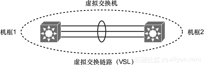
虛擬交換鏈路(VSL)是一條特殊的鏈路,它負責承載VSS兩臺交換機之間的控制流量和數據流量,詳見圖1-12。VSL通常被配置為EtherChannel,最多支持8條鏈路捆綁在一起。并不是只有這種特殊用途的鏈路能夠在VSS對等體之間提供通信路徑,但它的優勢是能夠為控制和管理平面的流量提供更高的優先級,使其優先于數據流量,從而保障控制和管理消息從不會被丟棄。多條VSL鏈路之間的數據流量負載均衡可以通過默認的方法實現,也可以通過配置EtherChannel負載均衡算法來實現。
1.6.4 多機框EtherChannel(MEC)
讀者從前文中已經可以看出EtherChannel的重要性了。EtherChannel(也可以稱為Port-Channel)是兩條或多條物理鏈路的集合,將這些物理鏈路合并成為一條邏輯鏈路。EtherChannel作為一個單獨的邏輯實體,交換機可以在它之上運行二層協議。這一概念也使另一些協議進行了相應調整,比如生成樹協議(STP),STP通常會阻塞設備之間的冗余鏈路,以防止產生交換環路。但我們這里所描述的概念是一種特殊類型的Port-Channel,它不僅可以建立在兩臺物理設備之間,還可以建立在多個機框(Chassis)之間;提供了普通EtherChannel環境中無法提供的硬件或設備故障倒換功能。這是因為VSS能夠創建MEC,而MEC這個EtherChannel中的成員接口可以分布在多臺VSS成員交換機上。非VSS交換機連接到VSS的話,MEC在它看來就是標準的EtherChannel,非VSS交換機可以使用雙站(Dual-Homed)的方式進行連接。流經MEC的流量可以在VSS成員交換機中實現負載均衡,這與標準EtherChannel非常類似。Cisco MEC支持動態EtherChannel協議,包括工業標準的LACP(鏈路匯聚控制協議)和Cisco私有的PAgP(端口匯聚協議),MEC還支持靜態EtherChannel配置。總的來說,VSS最多可以支持256條EtherChannel,這一數量限制是普通EtherChannel和MEC的總和。
1.6.5 基本VSS配置
為了創建VSS所需的最基本配置,首先需要在VSS的兩臺設備上創建相同的虛擬交換域。在VSS的兩臺交換機上,這個交換域體現為一個編號,這個編號必須在1~255的范圍內。在分配好域編號后,工程是必須將其中一臺路由器配置為switch 1,另一臺交換機配置為switch 2,如例1-8所示。
例1-8 分配虛擬交換域和交換機號碼
SW1# conf t
Enter configuration commands, one per line. End with CNTL/Z.
SW1(config)# switch virtual domain 10
Domain ID 10 config will take effect only
after the exec command 'switch convert mode virtual' is issued
SW1(config-vs-domain)# switch 1
SW1(config-vs-domain)# exit
SW1(config)#SW2# conf t
Enter configuration commands, one per line. End with CNTL/Z.
SW2(config)# switch virtual domain 10
Domain ID 10 config will take effect only
after the exec command 'switch convert mode virtual' is issued
SW2(config-vs-domain)# switch 2
SW2(config-vs-domain)# exit
SW2(config)#
接下來,工程師需要創建VSL,這需要在每臺交換機上都創建一個唯一的Port-Channel,詳見例1-9。在配置過程中,兩個Port-Channel都是在VSS主動交換機上建立的。如果VSS備用交換機的VSL Port-Channel號碼已經用于了其他用途,VSS將會啟動為路由處理器冗余模式。為了避免這種情況,要確保使用的Port-Channel號碼在兩臺交換機上都是可用的。例1-9 配置VSL Port-ChannelSW1(config)# int port-channel 5
SW1(config-if)# switchport
SW1(config-if)# switch virtual link 1
SW1(config-if)# no shut
SW1(config-if)# exit
*Jan 24 05:19:57.092: %SPANTREE-6-PORTDEL_ALL_VLANS: Port-channel5 deleted from allVlansSW2(config)# int port-channel 10
SW2(config-if)# switchport
SW2(config-if)# switch virtual link 2
SW2(config-if)# no shut
SW2(config-if)# exit
SW2(config)#
*Jan 24 05:14:17.273: %SPANTREE-6-PORTDEL_ALL_VLANS: Port-channel10 deleted fromall Vlans
現在已經配置好Port-Channel接口了,接下來需要將VSL物理成員接口添加到相應的Port-Channel中。在例1-10中,SW1上的接口GE 7/3和7/4將要與SW2上的接口GE 4/45和4/46連接在一起。例1-10 配置VSL接口SW1(config)# int range gig7/3 - 4
SW1(config-if-range)# switchport mode trunk
SW1(config-if-range)# channel-group 5 mode on
WARNING: Interface GigabitEthernet7/3 placed in restricted config mode. Allextraneous configs removed!
WARNING: Interface GigabitEthernet7/4 placed in restricted config mode. Allextraneous configs removed!
SW1(config-if-range)# exitSW2(config)# int range gig4/45 - 46
SW2(config-if-range)# switchport mode trunk
SW2(config-if-range)# channel-group 10 mode on
WARNING: Interface GigabitEthernet4/45 placed in restricted config mode. Allextraneous configs removed!
WARNING: Interface GigabitEthernet4/46 placed in restricted config mode. Allextraneous configs removed!
SW2(config-if-range)# exit
注釋:
在使用channel-group命令將接口放入VSL Port-Channel后,接口會進入“notconnect(無連接)”狀態。接口狀態會顯示為“up”,但線路協議狀態將顯示為“down”。在交換機重啟之前,接口將一直為up/down (notconnect)狀態。
接著工程師需要在SW1上使用命令switch convert mode virtual,完成交換機轉換過程。系統會提示工程師確認這一行為,這時輸入yes,詳見例1-11。這時系統會創建一個轉換配置文件,并存入系統的bootflash中。在兩臺交換機上都確認完畢后,運行配置文件(running-config)會被保存為啟動配置文件(startup-config),并且交換機會重啟。重啟后,交換機就進入了虛擬交換模式。例1-11 將交換機轉換為虛擬交換模式SW1# switch convert mode virtualThis command will convert all interface names
to naming convention "interface-type switch-number/slot/port",
save the running config to startup-config andreload the switch.
Do you want to proceed? [yes/no]: yes
Converting interface names
Building configuration...
Compressed configuration from 6551 bytes to 2893 bytes[OK]
Saving converted configuration to bootflash: ...
Destination filename [startup-config.converted_vs-20130124-062921]?
Please stand by while rebooting the system...
Restarting system.Rommon (G) Signature verification PASSED
Rommon (P) Signature verification PASSED
FPGA  (P) Signature verification PASSEDSimilarly you need to enter the "switch convert mode virtual" command on Switch 2for converting to Virtual Switch Mode.SW2# switch convert mode virtualThis command will convert all interface names
to naming convention "interface-type switch-number/slot/port",
save the running config to startup-config and
reload the switch.
Do you want to proceed? [yes/no]: yes
Converting interface names
Building configuration...
Compressed configuration from 6027 bytes to 2774 bytes[OK]
Saving converted configuration to bootflash: ...
Destination filename [startup-config.converted_vs-20130124-052526]?
Please stand by while rebooting the system...
Restarting system.Rommon (G) Signature verification PASSED
Rommon (P) Signature verification PASSED
FPGA  (P) Signature verification PASSED************************************************************
*                                *
* Welcome to Rom Monitor for WS-X45-SUP7-E System.     *
* Copyright (c) 2008-2012 by Cisco Systems, Inc.      *
* All rights reserved.                     *
*                                *
************************************************************
1.6.6 VSS檢查過程
工程師可以使用簡單的show命令來查看與特定VSS對相關的VSS配置信息,通過命令show switch virtual可以查看每臺交換機的交換機號碼和角色,詳見例1-12。
例1-12 查看虛擬交換域編號
SW1# sh switch virtualExecuting the command on VSS member switch role = VSS Active, id = 1Switch mode           : Virtual Switch
Virtual switch domain number  : 10
Local switch number       : 1
Local switch operational role  : Virtual Switch Active
Peer switch number        : 2
Peer switch operational role  : Virtual Switch StandbyExecuting the command on VSS member switch role = VSS Standby, id = 2Switch mode            : Virtual Switch
Virtual switch domain number  : 10
Local switch number       : 2
Local switch operational role  : Virtual Switch Standby
Peer switch number        : 1
Peer switch operational role  : Virtual Switch Active
要想讓VSS正常運行,最重要的一點是確保一臺交換機是主用交換機,另一臺是備用交換機。備用交換機的控制模式應該與例1-13所示相同。例1-13 備用交換機的控制模式SW2-standby>
Standby console disabled
正如理論部分所討論的,對于VSS來說,有很多角色和配置要求。工程師可以使用命令show switch virtual role來查看VSS中每臺交換機的變量。例1-14展示了使用這條命令輸出的類型和詳細信息。
工程師可以使用命令show switch virtual link來查看有關VSL的信息,詳見例1-15。
例1-14 虛擬角色分配和優先級
SW1# sh switch virtual role
Executing the command on VSS member switch role = VSS Active, id = 1
RRP information for Instance 1
--------------------------------------------------------------------
Valid Flags  Peer    Preferred ReservedCount    Peer    Peer
--------------------------------------------------------------------
TRUE  V     1       1     1
Switch Switch Status Preempt    Priority Role   Local    RemoteNumber     Oper(Conf)  Oper(Conf)      SID    SID
--------------------------------------------------------------------
LOCAL  1   UP    FALSE(N )  100(100) ACTIVE   0      0
REMOTE 2   UP    FALSE(N )  100(100) STANDBY   6834   6152Peer 0 represents the local switchFlags : V - Valid
In dual-active recovery mode: NoExecuting the command on VSS member switch role = VSS Standby, id = 2RRP information for Instance 2--------------------------------------------------------------------
Valid Flags  Peer    Preferred ReservedCount      Peer    Peer--------------------------------------------------------------------
TRUE  V   1         1      1Switch Switch Status Preempt    Priority Role    Local    RemoteNumber    Oper(Conf)  Oper(Conf)      SID    SID
--------------------------------------------------------------------
LOCAL  2   UP   FALSE(N )   100(100) STANDBY  0    0
REMOTE 1   UP   FALSE(N )   100(100) ACTIVE   6152    6834Peer 0 represents the local switchFlags : V - Valid
In dual-active recovery mode: No
例1-15 虛擬交換鏈路詳情SW1# sh switch virtual linkExecuting the command on VSS member switch role = VSS Active, id = 1VSL Status : UP
VSL Uptime : 3 minutes
VSL Control Link : Gi1/7/4Executing the command on VSS member switch role = VSS Standby, id = 2VSL Status : UP
VSL Uptime : 3 minutes
VSL Control Link : Gi2/4/45
除此之外,工程師還可以使用命令show switch virtual link port-channel來查看有關VSL Port-Channel配置的信息,詳見例1-16。
例1-16 查看VSL Port-Channel
SW1# sh switch virtual link port-channelExecuting the command on VSS member switch role = VSS Active, id = 1Flags: D - dow-     P - bundled in port-channelI - stand-alone s - suspendedH - Hot-standby (LACP only)R - Layer3    S - Layer2U - in use    N - not in use, no aggregationf - failed to allocate aggregatorM - not in use, no aggregation due to minimum links not metm - not in use, port not aggregated due to minimum links not metu - unsuitable for bundlingd - default portw - waiting to be aggregatedGroup Port-channel Protocol Ports
------+-------------+---------+-------------------
5   Po5(SU)      -    Gi1/7/3(P) Gi1/7/4(P)
10   Po10(SU)     -    Gi2/4/45(P) Gi2/4/46(P)Executing the command on VSS member switch role = VSS Standby, id = 2Flags: D - dow-      P - bundled in port-channelI - stand-alone s - suspendedH - Hot-standby (LACP only)R - Layer3    S - Layer2U - in use    N - not in use, no aggregationf - failed to allocate aggregatorM - not in use, no aggregation due to minimum links not metm - not in use, port not aggregated due to minimum links not metu - unsuitable for bundlingd - default portw - waiting to be aggregatedGroup Port-channel Protocol Ports
------+-------------+-----------+-------------------
5   Po5(SU)      -     Gi1/7/3(P) Gi1/7/4(P)
10   Po10(SU)     -     Gi2/4/45(P) Gi2/4/46(P)SW1#


)
)


)

![JS Ajax異步請求發送列表數據后面多了[]](http://pic.xiahunao.cn/JS Ajax異步請求發送列表數據后面多了[])


》一 導讀)

