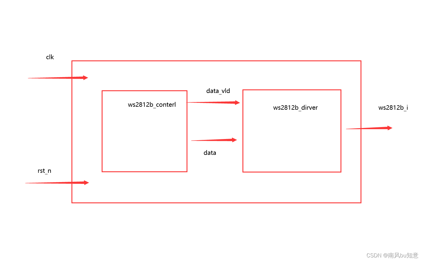
一,系統架構
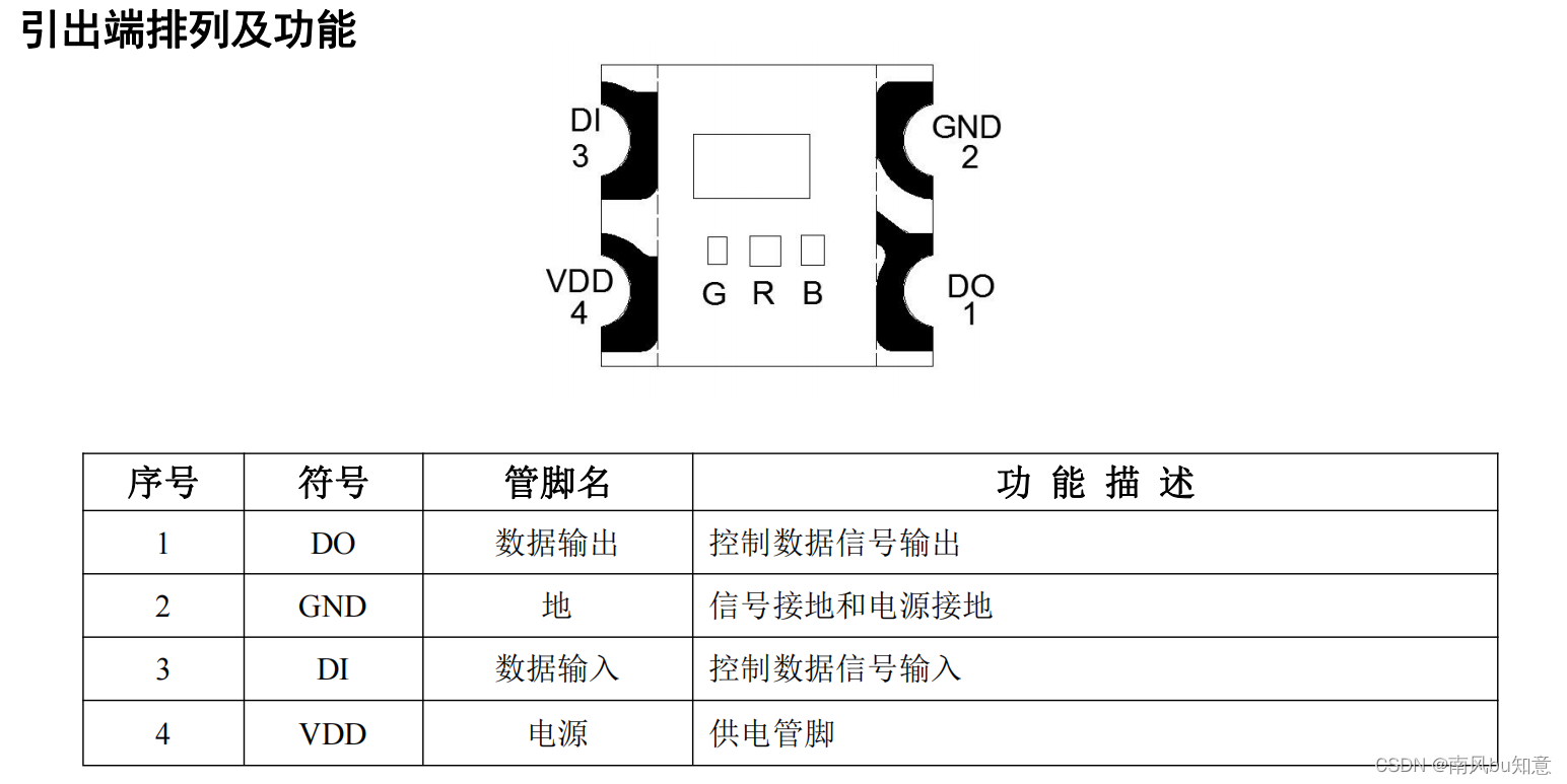
二,芯片介紹
1.管腳說明
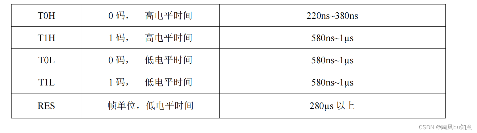
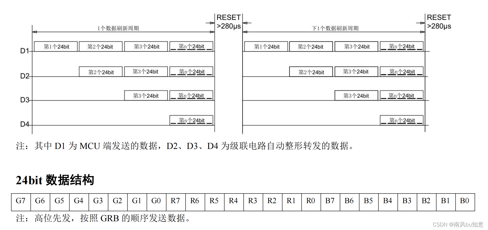
2.數據傳輸時間
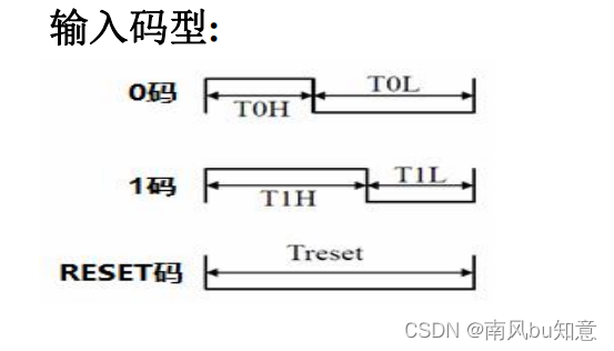
3.時序波形
4.數據傳輸方法
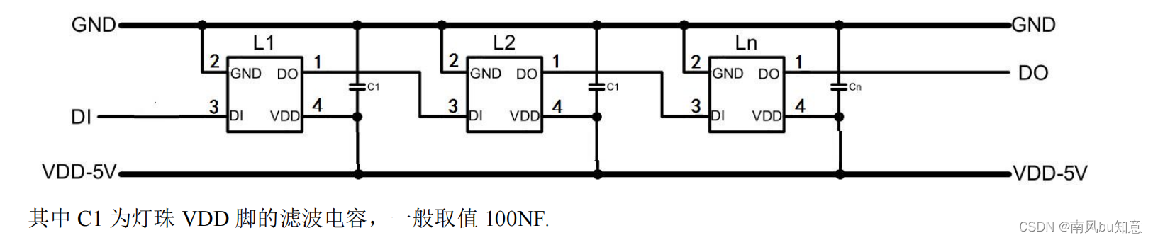
5.常用電路連接
三,代碼展示及說明
- 驅動模塊
在驅動模塊首先選擇使用狀態機,其中包括,空閑狀態,復位清空狀態,和讀數據狀態,其中空閑狀態是向fifo中寫入數據,復位清空狀態是清空ws2812b中的數據,讀數據狀態是講fifo中存的數據依次讀到ws2812b中,以這樣的流程來達到對ws2812b的控制,以下是我的驅動代碼:
/**************************************功能介紹***********************************
Date	:
Author	: WZY.
Version	:
Description: 這是項目的邏輯狀態機模塊
*********************************************************************************///---------<模塊及端口聲名>------------------------------------------------------
module state( input 	wire				clk		,input 	wire				rst_n	,input   wire    [23:0]      data_in ,input   wire                fifo_wr_vld,output  reg                 ws2812b_io ,output  wire                ready
);
//---------<參數定義>--------------------------------------------------------- //狀態機參數定義parameter IDLE = 3'b001,//空閑狀態RST  = 3'b010,//復位狀態DATA = 3'b100;//數據傳輸狀態    //---------<內部信號定義>-----------------------------------------------------reg 	[2:0]	cstate      ;//現態
reg	    [2:0]	nstate      ;//次態
wire            idle2rst    ;
wire            rst2data    ;
wire            data2idle   ;//fifoIP核參數定義
wire    [23:0]  fifo_wr_data;
wire    [23:0]  fifo_rd_data;
wire            empty       ;
wire            full        ;
wire            fifo_rd_req ;
wire            fifo_wr_req ;//復位參數定義
reg			[14:0]	cnt_rst	   	;
wire				add_cnt_rst	;
wire				end_cnt_rst	;//數據傳輸參數定義
reg			[5:0]	cnt_cyc	   	;
wire				add_cnt_cyc	;
wire				end_cnt_cyc	;reg			[4:0]	cnt_bit	   	;
wire				add_cnt_bit	;
wire				end_cnt_bit	;reg			[5:0]	cnt_num	   	;
wire				add_cnt_num	;
wire				end_cnt_num	;//****************************************************************
//                  狀態機
//****************************************************************//第一段:時序邏輯描述狀態轉移
always @(posedge clk or negedge rst_n)begin if(!rst_n)begincstate <= IDLE;end else begin cstate <= nstate;end
end//第二段:組合邏輯描述狀態轉移規律和狀態轉移條件
always @(*) begincase(cstate)IDLE  : beginif (idle2rst) beginnstate = RST;endelse beginnstate = cstate;endendRST   : beginif (rst2data) beginnstate = DATA;endelse beginnstate = cstate;endendDATA : beginif (data2idle) beginnstate = IDLE;endelse beginnstate = cstate;endenddefault : nstate = IDLE;endcase
end
assign idle2rst  = cstate == IDLE && fifo_wr_vld;//當檢測到讀使能時由空閑狀態轉換到復位狀態
assign rst2data  = cstate == RST  && end_cnt_rst;//當復位完成后轉到數據輸入狀態
assign data2idle = cstate == DATA && end_cnt_num;//當數據輸入完成后返回空閑狀態
//第三段:描述輸出,時序邏輯或組合邏輯皆可//****************************************************************
//                      IP核FIFO讀取
//****************************************************************
fifo_test	fifo_test_inst (.aclr ( ~rst_n ),.clock ( clk ),.data ( fifo_wr_data ),.rdreq ( fifo_rd_req ),.wrreq ( fifo_wr_req),.empty ( empty ),.full ( full ),.q ( fifo_rd_data ),.usedw (  ));       assign fifo_wr_data = {data_in[15:8],data_in[23:16],data_in[7:0]} ;//RGB->GRB
assign fifo_wr_req = fifo_wr_vld&&~full;//當檢測到寫使能并且不為滿時拉高
assign fifo_rd_req = end_cnt_bit&& ~empty;//每次讀取計時到一個數據后并且不為空時讀出一個數據//****************************************************************
//                  復位計時
//****************************************************************    always @(posedge clk or negedge rst_n)begin if(!rst_n)begincnt_rst <= 15'd0;end else if(add_cnt_rst)begin if(end_cnt_rst)begin cnt_rst <= 15'd0;endelse begin cnt_rst <= cnt_rst + 1'b1;end end
end assign add_cnt_rst = cstate == RST;
assign end_cnt_rst = add_cnt_rst && cnt_rst == 400_000/20 - 1;//****************************************************************
//                      數據傳輸計時
//****************************************************************always @(posedge clk or negedge rst_n)begin if(!rst_n)begincnt_cyc <= 6'd0;end else if(add_cnt_cyc)begin if(end_cnt_cyc)begin cnt_cyc <= 6'd0;endelse begin cnt_cyc <= cnt_cyc + 1'b1;end end
end assign add_cnt_cyc = cstate == DATA;
assign end_cnt_cyc = add_cnt_cyc && cnt_cyc == 1200/20 - 1;always @(posedge clk or negedge rst_n)begin if(!rst_n)begincnt_bit <= 5'd0;end else if(add_cnt_bit)begin if(end_cnt_bit)begin cnt_bit <= 5'd0;endelse begin cnt_bit <= cnt_bit + 1'b1;end end
end assign add_cnt_bit = end_cnt_cyc;
assign end_cnt_bit = add_cnt_bit && cnt_bit == 24-1;always @(posedge clk or negedge rst_n)begin if(!rst_n)begincnt_num <= 6'd0;end else if(add_cnt_num)begin if(end_cnt_num)begin cnt_num <= 6'd0;endelse begin cnt_num <= cnt_num + 1'b1;end end
end assign add_cnt_num = end_cnt_bit;
assign end_cnt_num = add_cnt_num && cnt_num == 64-1;
//****************************************************************
//                      用戶接口
//****************************************************************always @(posedge clk or negedge rst_n) begincase (cstate)IDLE : ws2812b_io = 0;RST  : ws2812b_io = 0;DATA : beginif (fifo_rd_data[23-cnt_bit] == 1) beginws2812b_io = (cnt_cyc <30)?1:0;endelse  beginws2812b_io = (cnt_cyc<15)?1:0;endenddefault: ws2812b_io = 0;endcase
end//****************************************************************
//                      ready控制
//****************************************************************
assign ready = cstate == IDLE;
endmodule
- 數據傳輸
接下來是數據選擇傳輸模塊,這個模塊同樣使用到了ip核以及狀態機,通過三個狀態,空閑狀態,讀數據狀態,以及延遲狀態,其中空閑狀態下,等待驅動模塊準備完成跳轉到讀數據狀態,在讀數據狀態下根據三個計數器即橫坐標,縱坐標還有偏移坐標來作為ROM的地址,依次向外讀出數據,同時驅動模塊向fifo中寫入數據,當讀取完64個數據后跳轉到等待狀態,延遲500ms后再次回到IDLE狀態并且偏移坐標+1,以此循環就可以達到動態顯示,下面是代碼展示:
/**************************************************************
@File    :   ws2812_control2.v
@Time    :   2023/08/14 10:04:56
@Author  :   WangHaodong
@EditTool:   VS Code
@Font    :   UTF-8
@Function:   顯示一張圖片
**************************************************************/
module ws2812_control(input               clk             ,input               rst_n           ,output      [23:0]  pix_data        ,output              pix_data_vld    ,input               ready                   //可以接收圖像數據了
);parameter   IDLE    =   0,DATA     =   1,DELAY     =   2;reg     [2:0]   state   ;reg	[5:0] cnt_x;wire		  add_x_cnt,end_x_cnt;	reg	[4:0] cnt_y;wire		  add_y_cnt,end_y_cnt;	reg			[24:0]	cnt_delay	   	;wire				add_cnt_delay	;wire				end_cnt_delay	;reg			[5:0]	cnt_offset	   	;wire				add_cnt_offset	;wire				end_cnt_offset	;localparam	RED     =   24'hFF0000,   //紅色ORANGE  =   24'hFF8000,   //橙色YELLOW  =   24'hFFFF00,   //黃色GREEN   =   24'h00FF00,   //綠色CYAN    =   24'h00FFFF,   //青色BLUE    =   24'h0000FF,   //藍色PURPPLE =   24'h8000FF,   //紫色BLACK   =   24'h000000,   //黑色WHITE   =   24'hFFFFFF,   //白色GRAY    =   24'hC0C0C0;	  //灰色
parameter   MAX_500S =  24_999_999;wire        rom_rd_req      ;wire        rom_rd_data_vld ;reg         rom_rd_req_r1   ;reg         rom_rd_req_r2   ;/**************************************************************狀態機
**************************************************************/always@(posedge clk or negedge rst_n)if(!rst_n)state <= IDLE;else case(state)IDLE		:	if(ready)state <=DATA;DATA		:	if(end_y_cnt)state <=DELAY;DELAY       :   if (end_cnt_delay) state <= IDLE;default :	state <= IDLE;endcase
//****************************************************************
//                  延時計數器
//****************************************************************always @(posedge clk or negedge rst_n)begin if(!rst_n)begincnt_delay <= 'd0;end else if(add_cnt_delay)begin if(end_cnt_delay)begin cnt_delay <= 'd0;endelse begin cnt_delay <= cnt_delay + 1'b1;end endelse begincnt_delay <= 0;end
end assign add_cnt_delay = state == DELAY;
assign end_cnt_delay = add_cnt_delay && cnt_delay == MAX_500S;/**************************************************************圖像數據個數計數器
**************************************************************/
//橫坐標always@(posedge clk or negedge rst_n)	if(!rst_n)								cnt_x <= 'd0;						else    if(add_x_cnt) begin				if(end_x_cnt)						cnt_x <= 'd0;  				else									cnt_x <= cnt_x + 1'b1;		end											assign add_x_cnt = state == DATA;assign end_x_cnt = add_x_cnt && cnt_x == 8 - 1;//縱坐標always@(posedge clk or negedge rst_n)	if(!rst_n)								cnt_y <= 'd0;						else    if(add_y_cnt) begin				if(end_y_cnt)						cnt_y <= 'd0;  				else									cnt_y <= cnt_y + 1'b1;		end											assign add_y_cnt = end_x_cnt;assign end_y_cnt = add_y_cnt && cnt_y == 8 - 1;//偏移量  always @(posedge clk or negedge rst_n)begin if(!rst_n)begincnt_offset <= 'd0;end else if(add_cnt_offset)begin if(end_cnt_offset)begin cnt_offset <= 'd0;endelse begin cnt_offset <= cnt_offset + 1'b1;end endend assign add_cnt_offset = end_cnt_delay;assign end_cnt_offset = add_cnt_offset && cnt_offset == 31;wire[4:0]  num_x;assign num_x = (cnt_x+cnt_offset)%32;//避免超出32的坐標限制//存放了一張圖片rom	rom_inst (.aclr       ( ~rst_n ),.address    (  cnt_y*32+num_x ),.clock      ( clk ),.rden       (rom_rd_req),.q          (pix_data));assign rom_rd_req = state == DATA;always@(posedge clk or negedge rst_n)if(!rst_n) beginrom_rd_req_r1 <= 0;rom_rd_req_r2 <= 0;endelse beginrom_rd_req_r1 <= rom_rd_req;rom_rd_req_r2 <= rom_rd_req_r1;endassign rom_rd_data_vld = rom_rd_req_r2;assign pix_data_vld = rom_rd_data_vld;//打兩拍使得讀出數據和fifo中寫入數據同步endmodule
3.仿真演示
仿真代碼:
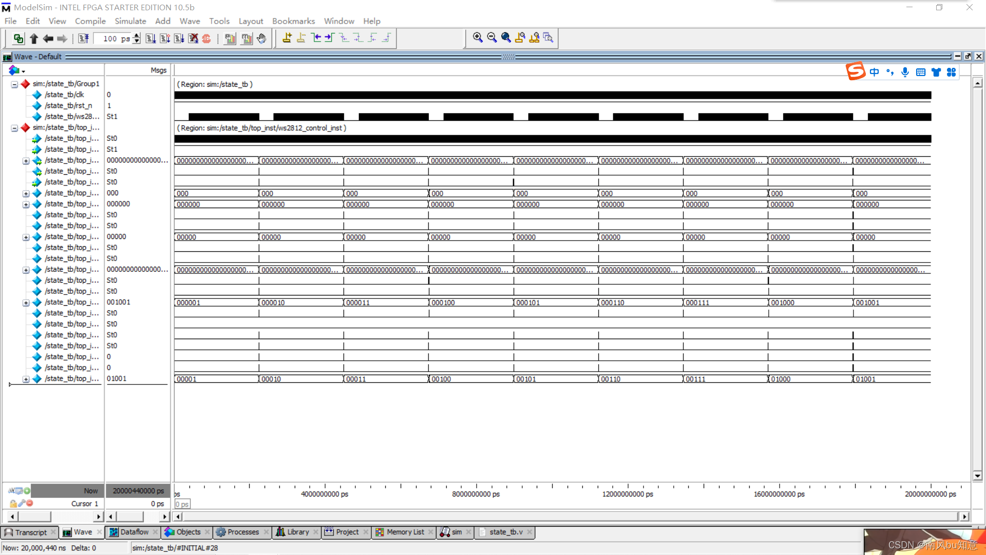
`timescale 1ns/1nsmodule state_tb();//激勵信號定義 reg				 clk  	;reg				 rst_n	;
//輸出信號定義	 wire                    ws2812b_io ;//時鐘周期參數定義	parameter		CYCLE = 20; defparam        top_inst.ws2812_control_inst.MAX_500S = 10*CYCLE;  //模塊例化top top_inst(.clk            (clk),.rst_n          (rst_n),.ws2812b_io     (ws2812b_io)
);	//產生時鐘initial 		 clk = 1'b1;always #(CYCLE/2)  clk = ~ clk;//產生激勵initial  begin rst_n = 1'b1;#(CYCLE*2);rst_n = 1'b0;#(CYCLE*20);rst_n = 1'b1;#(CYCLE*1000000);$stop;endendmodule
仿真結果展示:


(基于c語言的補充))
)


)


)

