1 HSRP配置 ? ?
1.1 問題
在企業網絡到外部的連接方案中,要求不高的條件下可以是單出口。一旦該出口線路出現問題,整個企業網絡就不能連接到外網了。為了使得企業網絡到外網連接的高可用性,可以設置兩個以上的出口,然而多個出口對于內網主機意味著我個網關。主機不能同時使用多個網關,當主機所使用的網關出現故障時,它不能實現網關的自動切換。
1)配置熱備份路由協議
1.2 方案
在出口設備上配置熱備份路由協議(HSRP),組成一個HSRP組,組內兩個出口設備共享一個虛擬IP地址,該IP地址作為內網主機的網關。
HSRP組成員有主備之分,虛擬IP地址被附加到主設備上。如果主設備線路出故障,備份設備會成為主設備,虛擬IP地址也會遷移過來。這樣,不管哪一個出口設備出現問題,不管哪個出口設備在提供外網接入,內網主機的網關都不需要改變。
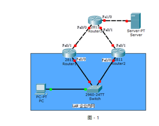
網絡拓撲圖如圖-1所示:
圖-1
?
?
藍色區域表示內網,上面模擬到外網的連接。
1.3 步驟
實現此案例需要按照如下步驟進行。
步驟一:分別在三臺路由器上配置端口IP地址
- tarena-R1(config)#int f0/0
- tarena-R1(config-if)#ip address 192.168.0.1 255.255.255.0
- tarena-R1(config-if)#no shutdown
- tarena-R1(config-if)#interface f0/1
- tarena-R1(config-if)#ip address 192.168.1.1 255.255.255.0
- tarena-R1(config-if)#no shutdown
- tarena-R2(config)#interface f0/0
- tarena-R2(config-if)#ip address 192.168.0.2 255.255.255.0
- tarena-R2(config-if)#no shutdown
- tarena-R2(config-if)#interface f0/1
- tarena-R2(config-if)#ip address 192.168.2.1 255.255.255.0
- tarena-R2(config-if)#no shutdown
- tarena-R3(config)#interface f0/0
- tarena-R3(config-if)#ip address 192.168.1.2 255.255.255.0
- tarena-R3(config-if)#no shutdown
- tarena-R3(config-if)#interface f0/1
- tarena-R3(config-if)#ip address 192.168.2.2 255.255.255.0
- tarena-R3(config-if)#no shutdown
- tarena-R3(config-if)#interface f1/0
- tarena-R3(config-if)#ip address 200.1.1.1 255.255.255.0
- tarena-R3(config-if)#no shutdown
步驟二:在R1和R2上配置到外網的默認路由
- tarena-R1(config)#ip route 0.0.0.0 0.0.0.0 192.168.1.2
- tarena-R1(config)#end
- tarena-R1#show ip route
- Codes: C - connected, S - static, I - IGRP, R - RIP, M - mobile, B - BGP
- D - EIGRP, EX - EIGRP external, O - OSPF, IA - OSPF inter area
- N1 - OSPF NSSA external type 1, N2 - OSPF NSSA external type 2
- E1 - OSPF external type 1, E2 - OSPF external type 2, E - EGP
- i - IS-IS, L1 - IS-IS level-1, L2 - IS-IS level-2, ia - IS-IS inter area
- * - candidate default, U - per-user static route, o - ODR
- P - periodic downloaded static route
- Gateway of last resort is 192.168.1.2 to network 0.0.0.0
- C 192.168.0.0/24 is directly connected, FastEthernet0/0
- C 192.168.1.0/24 is directly connected, FastEthernet0/1
- S* 0.0.0.0/0 [1/0] via 192.168.1.2
- tarena-R1#
- tarena-R2(config)#ip route 0.0.0.0 0.0.0.0 192.168.2.2
- tarena-R2(config)#exit
- tarena-R2#show ip route
- Codes: C - connected, S - static, I - IGRP, R - RIP, M - mobile, B - BGP
- D - EIGRP, EX - EIGRP external, O - OSPF, IA - OSPF inter area
- N1 - OSPF NSSA external type 1, N2 - OSPF NSSA external type 2
- E1 - OSPF external type 1, E2 - OSPF external type 2, E - EGP
- i - IS-IS, L1 - IS-IS level-1, L2 - IS-IS level-2, ia - IS-IS inter area
- * - candidate default, U - per-user static route, o - ODR
- P - periodic downloaded static route
- Gateway of last resort is 192.168.2.2 to network 0.0.0.0
- C 192.168.0.0/24 is directly connected, FastEthernet0/0
- C 192.168.2.0/24 is directly connected, FastEthernet0/1
- S* 0.0.0.0/0 [1/0] via 192.168.2.2
步驟三:在R3上配置到企業內網的靜態路由
- tarena-R3(config)#ip route 192.168.0.0 255.255.255.0 192.168.2.1
- tarena-R3(config)#ip route 192.168.0.0 255.255.255.0 192.168.1.1
- tarena-R3(config)#end
- tarena-R3#show ip route
- Codes: C - connected, S - static, I - IGRP, R - RIP, M - mobile, B - BGP
- D - EIGRP, EX - EIGRP external, O - OSPF, IA - OSPF inter area
- N1 - OSPF NSSA external type 1, N2 - OSPF NSSA external type 2
- E1 - OSPF external type 1, E2 - OSPF external type 2, E - EGP
- i - IS-IS, L1 - IS-IS level-1, L2 - IS-IS level-2, ia - IS-IS inter area
- * - candidate default, U - per-user static route, o - ODR
- P - periodic downloaded static route
- Gateway of last resort is not set
- S 192.168.0.0/24 [1/0] via 192.168.2.1
- [1/0] via 192.168.1.1
- C 192.168.1.0/24 is directly connected, FastEthernet0/0
- C 192.168.2.0/24 is directly connected, FastEthernet0/1
- C 200.1.1.0/24 is directly connected, FastEthernet1/0
- tarena-R3#
步驟四:在R1上配置HSRP,指定其優先級為200
HSRP的默認優先級為100,路由器啟動后,根據優先級決定誰可以成為活躍路由器,優先級高的將勝出。如果路由器優先級相同,再比較端口IP地址,IP地址大的成為活路躍路由器。
另外,如果優先級低的路由器先啟動了,它將成為活躍路由器。優先級高的路由器啟動后,發現已有活躍路由器存在,它將接受現狀,直到活躍路由器出現故障它才會在重新選舉時成為活躍角色。
- tarena-R1(config)#interface f0/0
- tarena-R1(config-if)#standby 1 ip 192.168.0.254
- tarena-R1(config-if)#standby 1 priority 200
- %HSRP-6-STATECHANGE: FastEthernet0/0 Grp 1 state Speak -> Standby
- %HSRP-6-STATECHANGE: FastEthernet0/0 Grp 1 state Standby -> Active
配置HSRP后,通過輸出日志可以觀察到路由器角色的改變。
步驟五:在R2上配置HSRP,指定其優先級為195
- tarena-R2(config)#interface f0/0
- tarena-R2(config-if)#standby 1 ip 192.168.0.254
- tarena-R2(config-if)#standby 1 priority 195
- %HSRP-6-STATECHANGE: FastEthernet0/0 Grp 1 state Speak -> Standby
步驟六:分別在R1和R2上查看HSRP信息
- tarena-R1#show standby brief
- P indicates configured to preempt.
- |
- Interface Grp Pri P State Active Standby Virtual IP
- Fa0/0 1 200 Active local 192.168.0.2 192.168.0.254
- tarena-R2#show standby brief
- P indicates configured to preempt.
- |
- Interface Grp Pri P State Active Standby Virtual IP
- Fa0/0 1 195 Standby 192.168.0.1 local 192.168.0.254
根據輸出信息,可以看到優先級大的R1成為了活躍路由器,繼續在其上面查看arp信息,能夠查看到虛擬IP地址被附加到R1上了。
- tarena-R1#show ip arp
- Protocol Address Age (min) Hardware Addr Type Interface
- Internet 192.168.0.1 - 0005.5E53.3001 ARPA FastEthernet0/0
- Internet 192.168.0.254 12 0000.0C9F.F001 ARPA FastEthernet0/0
- Internet 192.168.1.1 - 0005.5E53.3002 ARPA FastEthernet0/1
步驟七:在內部主機上測試到外網主機的連通性
- PC>ipconfig
- FastEthernet0 Connection:(default port)
- Link-local IPv6 Address.........: FE80::207:ECFF:FE80:557D
- IP Address......................: 192.168.0.10
- Subnet Mask.....................: 255.255.255.0
- Default Gateway.................: 192.168.0.254
- PC>ping 200.1.1.10
- Pinging 200.1.1.10 with 32 bytes of data:
- Reply from 200.1.1.10: bytes=32 time=0ms TTL=126
- Reply from 200.1.1.10: bytes=32 time=0ms TTL=126
- Reply from 200.1.1.10: bytes=32 time=0ms TTL=126
- Reply from 200.1.1.10: bytes=32 time=1ms TTL=126
- Ping statistics for 200.1.1.10:
- Packets: Sent = 4, Received = 4, Lost = 0 (0% loss),
- Approximate round trip times in milli-seconds:
- Minimum = 0ms, Maximum = 1ms, Average = 0ms
- PC>tracert 200.1.1.10
- Tracing route to 200.1.1.10 over a maximum of 30 hops:
- 1 0 ms 1 ms 0 ms 192.168.0.1
- 2 0 ms 1 ms 0 ms 192.168.1.2
- 3 0 ms 0 ms 0 ms 200.1.1.10
- Trace complete.
- PC>
Ping命令只能檢測網絡是否連通,如果要查看具體路徑需要使用tracert。根據tracert顯示結果,R1轉發了PC機的數據包。
步驟八:關閉R1電源,模擬設備故障,查看R2的HSRP信息
- tarena-R2#
- %HSRP-6-STATECHANGE: FastEthernet0/0 Grp 1 state Standby -> Active
- tarena-R2#show standby brief
- P indicates configured to preempt.
- |
- Interface Grp Pri P State Active Standby Virtual IP
- Fa0/0 1 195 Active local unknown 192.168.0.254
- tarena-R2#show ip arp
- Protocol Address Age (min) Hardware Addr Type Interface
- Internet 192.168.0.2 - 0001.4200.9C01 ARPA FastEthernet0/0
- Internet 192.168.0.10 9 0007.EC80.557D ARPA FastEthernet0/0
- Internet 192.168.0.254 1 0000.0C9F.F001 ARPA FastEthernet0/0
- Internet 192.168.2.1 - 0001.4200.9C02 ARPA FastEthernet0/1
- Internet 192.168.2.2 9 0005.5E59.E002 ARPA FastEthernet0/1
結果顯示R2已成為活躍路由器,而備份路由器狀態未知。虛擬路由器的IP地址192.168.0.254/24也已遷移到R2上了。
步驟九:再次在內部主機上測試到外網主機的連通性
- PC>ping 200.1.1.10
- Pinging 200.1.1.10 with 32 bytes of data:
- Reply from 200.1.1.10: bytes=32 time=0ms TTL=126
- Reply from 200.1.1.10: bytes=32 time=1ms TTL=126
- Reply from 200.1.1.10: bytes=32 time=1ms TTL=126
- Reply from 200.1.1.10: bytes=32 time=0ms TTL=126
- Ping statistics for 200.1.1.10:
- Packets: Sent = 4, Received = 4, Lost = 0 (0% loss),
- Approximate round trip times in milli-seconds:
- Minimum = 0ms, Maximum = 1ms, Average = 0ms
- PC>tracert 200.1.1.10
- Tracing route to 200.1.1.10 over a maximum of 30 hops:
- 1 1 ms 0 ms 0 ms 192.168.0.2
- 2 0 ms 0 ms 0 ms 192.168.2.2
- 3 0 ms 1 ms 0 ms 200.1.1.10
- Trace complete.
- PC>
根據tracert結果,路由器R2轉發了PC機的數據包
步驟十:再次在內部主機上測試到外網主機的連通性
備份路由器成為活躍路由器后,原來的活躍路由器R1即使線路修復也不會重新成為進入活躍狀態。
為了使路由器完全根據優先級來決定其狀態,需要配置占先權。占先權保證了嚴格根據優先級來決定哪臺設備進入活躍狀態。
- tarena-R1(config)#interface f0/0
- tarena-R1(config-if)#standby 1 preempt
- tarena-R2(config)#interface f0/0
- tarena-R2(config-if)#standby 1 preempt
2 PVST+的配置
2.1 問題
二層網絡中有可能出現因為線路故障而導致的通信故障,通過冗余線路可以消除因為某一線路故障而導致的網絡中斷。
但是因為冗余線路的存在,又可能會出現廣播風暴、相同幀的不斷復制和MAC地址表不穩定。
1)配置Switch1為vlan1的主根,Switch2為vlan1的次根
2.2 方案
為了保證在冗余環境下不會出廣播風暴等問題,引入了生成樹(STP)協議。通過生成樹協議可以把冗余線路上的某一個端口置為阻塞(BLOCKING)狀態,防止廣播風暴的產生,當某一線路出現故障時,被阻塞的端口自動進入轉發(FORWARDING)狀態,保證網絡的暢通性。
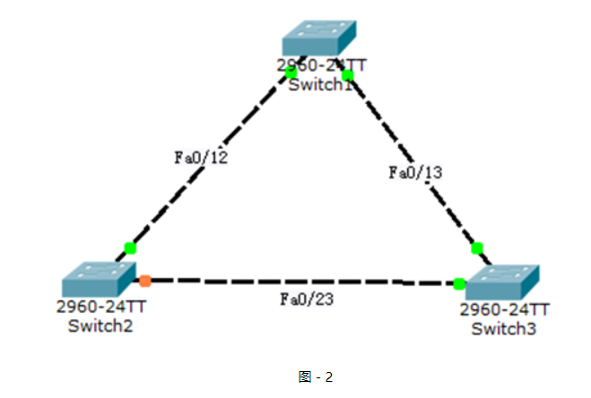
網絡拓撲如圖-2所示:
圖-2
?
?
?
2.3 步驟
實現此案例需要按照如下步驟進行。
步驟一:將三臺交換機相連的端口配置為中繼端口
- tarena-sw1(config)#interface range f0/12 -13
- tarena-sw1(config-if-range)#switchport mode trunk
- tarena-sw2(config)#interface range f0/12, f0/23
- tarena-sw2(config-if-range)#switchport mode trunk
- tarena-sw3(config)#interface range f0/13 ,f0/23
- tarena-sw3(config-if-range)#switchport mode trunk
步驟二:設置tarena-sw1為根網橋
根網橋唯一的依據是BID最小。BID分為兩個部分:優先級+MAC地址。比較BID時,先比較優先級,如果優先級相同才比較MAC地址。
優先級取值范圍是0到65535,默認值為32768。在查看優先級時,即使是默認值看到的也不是32768,因為交換機的優先級采用系統優先級+VLAN編號的方式,所以查看到的VLAN1默認優先級是32769(系統優先級32768+VLAN編號1)。
- tarena-sw1(config)#spanning-tree vlan 1 root primary
- tarena-sw1(config)#exit
- tarena-sw1#show spanning-tree
- VLAN0001
- Spanning tree enabled protocol ieee
- Root ID Priority 24577 //默認優先級為32768
- Address 0060.478B.607B
- This bridge is the root
- Hello Time 2 sec Max Age 20 sec Forward Delay 15 sec
- Bridge ID Priority 24577 (priority 24576 sys-id-ext 1)
- Address 0060.478B.607B
- Hello Time 2 sec Max Age 20 sec Forward Delay 15 sec
- Aging Time 20
- Interface Role Sts Cost Prio.Nbr Type
- ----------- ------ --- -------- -------- ----------------------
- Fa0/13 Desg FWD 19 128.13 P2p
- Fa0/12 Desg FWD 19 128.12 P2p
查看到的結果,Root ID部分指的是根網橋信息,Bridge ID部分是當前所操作的交換機信息,如果二者一致表示當前操作的交換機就是根網橋。
步驟三:設置tarena-sw2為次根,即BID值大小居中
- tarena-sw2(config)#spanning-tree vlan 1 root secondary
- tarena-sw2#show spanning-tree
- VLAN0001
- Spanning tree enabled protocol ieee
- Root ID Priority 24577 //此處雖然與tarena-sw1一樣,但MAC地址更大
- Address 0060.478B.607B
- Cost 19
- Port 12(FastEthernet0/12)
- Hello Time 2 sec Max Age 20 sec Forward Delay 15 sec
- Bridge ID Priority 28673 (priority 28672 sys-id-ext 1)
- Address 0090.0C77.8924
- Hello Time 2 sec Max Age 20 sec Forward Delay 15 sec
- Aging Time 20
- Interface Role Sts Cost Prio.Nbr Type
- ---------- ---- ---- ----- -------- ---------
- Fa0/12 Root FWD 19 128.12 P2p
- Fa0/23 Desg FWD 19 128.23 P2p
步驟四:tarena-sw3不需要做改動,直接查看STP狀態
- tarena-sw3#show spanning-tree
- VLAN0001
- Spanning tree enabled protocol ieee
- Root ID Priority 24577
- Address 0060.478B.607B
- Cost 19
- Port 13(FastEthernet0/13)
- Hello Time 2 sec Max Age 20 sec Forward Delay 15 sec
- Bridge ID Priority 32769 (priority 32768 sys-id-ext 1)
- Address 0060.5C9E.2E75
- Hello Time 2 sec Max Age 20 sec Forward Delay 15 sec
- Aging Time 20
- Interface Role Sts Cost Prio.Nbr Type
- ---------- ------ ---- ----- -------- ----------
- Fa0/13 Root FWD 19 128.13 P2p
- Fa0/23 Altn BLK 19 128.23 P2p
觀察Sts列(即狀態status),Fa0/23端口當前是耳塞(BLK)狀態,即該端口不能轉發數據。
步驟五:模擬交換機間線纜故障。將tarena-sw2的Fa0/12口shutdown,再次檢查tarena-sw3端口狀態
- tarena-sw2(config)#interface f0/12
- tarena-sw2(config-if)#shutdown
- tarena-sw3#show spanning-tree
- VLAN0001
- Spanning tree enabled protocol ieee
- Root ID Priority 24577
- Address 0060.478B.607B
- Cost 19
- Port 13(FastEthernet0/13)
- Hello Time 2 sec Max Age 20 sec Forward Delay 15 sec
- Bridge ID Priority 32769 (priority 32768 sys-id-ext 1)
- Address 0060.5C9E.2E75
- Hello Time 2 sec Max Age 20 sec Forward Delay 15 sec
- Aging Time 20
- Interface Role Sts Cost Prio.Nbr Type
- ---------- ------ ---- ----- -------- ----------
- Fa0/13 Root FWD 19 128.13 P2p
- Fa0/23 Desg FWD 19 128.23 P2p
從tarena-sw3的輸出可以看到,Fa0/23端口已從阻塞狀態切換到轉發(FWD)狀態,保證了網絡的暢通。當線路恢復(在rarena-sw2的Fa0/12端口執行no shutdown)后,tarena-sw3的Fa0/23端口將重新進入阻塞狀態以網止環路的產生。
在查看時,tarena-sw3的Fa0/23端口不是立即進入轉發或是阻塞狀態。生成樹端口有阻塞,偵聽,學習和轉發四個狀態,當拓撲變化時,端口狀態改變要遵從這些狀態的逐漸改變。
?
1 配置標準ACL
1.1 問題
絡調通后,保證網絡是通暢的。同時也很可能出現未經授權的非法訪問。企業網絡既要解決連連通的問題,還要解決網絡安全的問題。
1)配置標準ACL實現拒絕PC2(IP地址為192.168.0.20)對Web Server P的瀏覽器訪問
1.2 方案
訪問控制是網絡安全防范和保護的主要策略,它的主要任務是保證網絡資源不被非法使用和訪問。它是保證網絡安全最重要的核心策略之一。
訪問控制列表(Access Control Lists,ACL)是應用在路由器接口的指令列表。這些指令列表用來告訴路由器哪能些數據包可以收、哪能數據包需要拒絕。至于數據包是被接收還是拒絕,可以由類似于源地址、目的地址、端口號等的特定指示條件來決定。
標準訪問控制列表只能根據數據包的源IP地址決定是否允許通過。
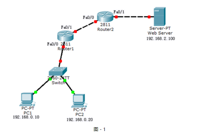
網絡拓撲如圖-1所示:
圖-1
?
1.3 步驟
實現此案例需要按照如下步驟進行。
步驟一:在R1上配置IP地址及靜態路由
- tarena-R1(config)#interface f0/0
- tarena-R1(config-if)#ip address 192.168.0.1 255.255.255.0
- tarena-R1(config-if)#no shutdown
- tarena-R1(config-if)#interface f0/1
- tarena-R1(config-if)#ip address 192.168.1.1 255.255.255.0
- tarena-R1(config-if)#no shutdown
- tarena-R1(config-if)#exit
- tarena-R1(config)#ip route 192.168.2.0 255.255.255.0 192.168.1.2
步驟二:在R2上配置IP地址及靜態路由
- tarena-R2(config)#interface f0/0
- tarena-R2(config-if)#ip address 192.168.1.2 255.255.255.0
- tarena-R2(config-if)#no shutdown
- tarena-R2(config-if)#interface f0/1
- tarena-R2(config-if)#ip address 192.168.2.1 255.255.255.0
- tarena-R2(config-if)#no shutdown
- tarena-R2(config-if)#exit
- tarena-R2(config)#ip route 192.168.0.0 255.255.255.0 192.168.1.1
步驟三:在R1和R2上檢查路由表
- tarena-R1#show ip route
- Codes: C - connected, S - static, I - IGRP, R - RIP, M - mobile, B - BGP
- D - EIGRP, EX - EIGRP external, O - OSPF, IA - OSPF inter area
- N1 - OSPF NSSA external type 1, N2 - OSPF NSSA external type 2
- E1 - OSPF external type 1, E2 - OSPF external type 2, E - EGP
- i - IS-IS, L1 - IS-IS level-1, L2 - IS-IS level-2, ia - IS-IS inter area
- * - candidate default, U - per-user static route, o - ODR
- P - periodic downloaded static route
- Gateway of last resort is not set
- C 192.168.0.0/24 is directly connected, FastEthernet0/0
- C 192.168.1.0/24 is directly connected, FastEthernet0/1
- S 192.168.2.0/24 [1/0] via 192.168.1.2
- tarena-R2#
- tarena-R2#show ip route
- Codes: C - connected, S - static, I - IGRP, R - RIP, M - mobile, B - BGP
- D - EIGRP, EX - EIGRP external, O - OSPF, IA - OSPF inter area
- N1 - OSPF NSSA external type 1, N2 - OSPF NSSA external type 2
- E1 - OSPF external type 1, E2 - OSPF external type 2, E - EGP
- i - IS-IS, L1 - IS-IS level-1, L2 - IS-IS level-2, ia - IS-IS inter area
- * - candidate default, U - per-user static route, o - ODR
- P - periodic downloaded static route
- Gateway of last resort is not set
- S 192.168.0.0/24 [1/0] via 192.168.1.1
- C 192.168.1.0/24 is directly connected, FastEthernet0/0
- C 192.168.2.0/24 is directly connected, FastEthernet0/1
步驟四:測試主機到Web Server的連通性
在實施ACL之前先檢查網絡是否能夠正常通信,因為沒有任何限制,網絡應該是處于連通狀態。
PC1測試如下所示:
- PC>ipconfig
- FastEthernet0 Connection:(default port)
- Link-local IPv6 Address.........: FE80::2E0:F7FF:FED6:54CC
- IP Address......................: 192.168.0.10
- Subnet Mask.....................: 255.255.255.0
- Default Gateway.................: 192.168.0.1
- PC>ping 192.168.2.100
- Pinging 192.168.2.100 with 32 bytes of data:
- Request timed out.
- Request timed out.
- Reply from 192.168.2.100: bytes=32 time=0ms TTL=126
- Reply from 192.168.2.100: bytes=32 time=0ms TTL=126
- Ping statistics for 192.168.2.100:
- Packets: Sent = 4, Received = 2, Lost = 2 (50% loss),
- Approximate round trip times in milli-seconds:
- Minimum = 0ms, Maximum = 0ms, Average = 0ms
- PC>
PC2測試如下所示:
- PC>ipconfig
- FastEthernet0 Connection:(default port)
- Link-local IPv6 Address.........: FE80::2D0:BAFF:FE98:9E29
- IP Address......................: 192.168.0.20
- Subnet Mask.....................: 255.255.255.0
- Default Gateway.................: 192.168.0.1
- PC>ping 192.168.2.100
- Pinging 192.168.2.100 with 32 bytes of data:
- Reply from 192.168.2.100: bytes=32 time=2ms TTL=126
- Reply from 192.168.2.100: bytes=32 time=0ms TTL=126
- Reply from 192.168.2.100: bytes=32 time=0ms TTL=126
- Reply from 192.168.2.100: bytes=32 time=0ms TTL=126
- Ping statistics for 192.168.2.100:
- Packets: Sent = 4, Received = 4, Lost = 0 (0% loss),
- Approximate round trip times in milli-seconds:
- Minimum = 0ms, Maximum = 2ms, Average = 0ms
- PC>
步驟五:在R2上配置標準訪問控制列表,并應用到Fa0/1端口出方向上
標準訪問控制列表因為只能限制源IP地址,因此應該把ACL放到離目標最近的端口出方向上。
ACL的匹配規則中,最后有一條隱含拒絕全部。如果語句中全部是拒絕條目,那么最后必須存在允許語句,否則所有數據通信都將被拒絕。
- tarena-R2(config)#access-list 1 deny host 192.168.0.20
- tarena-R2(config)#access-list 1 permit any
- tarena-R2(config)#interface f0/1
- tarena-R2(config-if)#ip access-group 1 out
步驟六:分別在兩臺主機上測試到Web Server的連通性
PC1測試如下所示:
- PC>ipconfig
- FastEthernet0 Connection:(default port)
- Link-local IPv6 Address.........: FE80::2E0:F7FF:FED6:54CC
- IP Address......................: 192.168.0.10
- Subnet Mask.....................: 255.255.255.0
- Default Gateway.................: 192.168.0.1
- PC>ping 192.168.2.100
- Pinging 192.168.2.100 with 32 bytes of data:
- Reply from 192.168.2.100: bytes=32 time=1ms TTL=126
- Reply from 192.168.2.100: bytes=32 time=0ms TTL=126
- Reply from 192.168.2.100: bytes=32 time=0ms TTL=126
- Reply from 192.168.2.100: bytes=32 time=0ms TTL=126
- Ping statistics for 192.168.2.100:
- Packets: Sent = 4, Received = 4, Lost = 0 (0% loss),
- Approximate round trip times in milli-seconds:
- Minimum = 0ms, Maximum = 1ms, Average = 0ms
- PC>
PC2測試如下所示:
- PC>ipconfig
- FastEthernet0 Connection:(default port)
- Link-local IPv6 Address.........: FE80::2D0:BAFF:FE98:9E29
- IP Address......................: 192.168.0.20
- Subnet Mask.....................: 255.255.255.0
- Default Gateway.................: 192.168.0.1
- PC>ping 192.168.2.100
- Pinging 192.168.2.100 with 32 bytes of data:
- Reply from 192.168.1.2: Destination host unreachable.
- Reply from 192.168.1.2: Destination host unreachable.
- Reply from 192.168.1.2: Destination host unreachable.
- Reply from 192.168.1.2: Destination host unreachable.
- Ping statistics for 192.168.2.100:
- Packets: Sent = 4, Received = 0, Lost = 4 (100% loss),
- PC>
結果顯示PC1(IP地址為192.168.0.10)可以正常訪問Web Server,而PC2(IP地址為192.168.0.20)已經被192.168.1.2(R2)拒絕。
步驟七:在R2上查看相關的ACL信息
- tarena-R2#show ip access-lists
- Standard IP access list 1
- deny host 192.168.0.20 (4 match(es))
- permit any (4 match(es))
?
2 配置擴展ACL
2.1 問題
在網絡中很有可能要允許或拒絕的并不是某一個源IP地址,而是根據目標地址或是協議來匹配。但是標準訪問控制列表只能根據源IP地址來決定是否允許一個數據包通過。
1)配置擴展ACL實現拒絕PC2(IP地址為192.168.0.20)訪問Web Server的web服務,但可訪問其他服務。
2.2 方案
為了實現更靈活、列精確的網絡控制就需要用到擴展訪問控制列表了。
擴展IP訪問控制列表比標準IP訪問控制列表具有更多的匹配項,包括協議類型、源地址、目的地址、源端口、目的端口、建立連接的和IP優先級等。
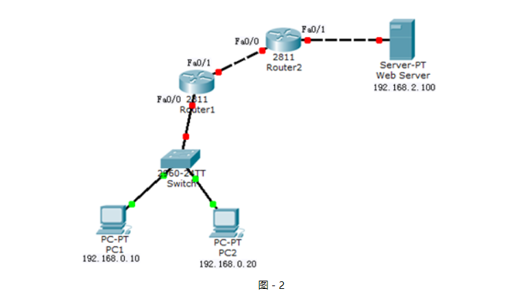
網絡拓撲如圖-2所示:
圖-2
?
2.3 步驟
實現此案例需要按照如下步驟進行。
步驟一:將1配置標準ACL中的標準訪問控制列表移除,其他配置保留
- tarena-R2(config)#interface f0/1
- tarena-R2(config-if)#no ip access-group 1 out
- tarena-R2(config)#no access-list 1
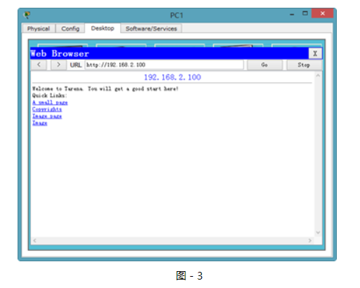
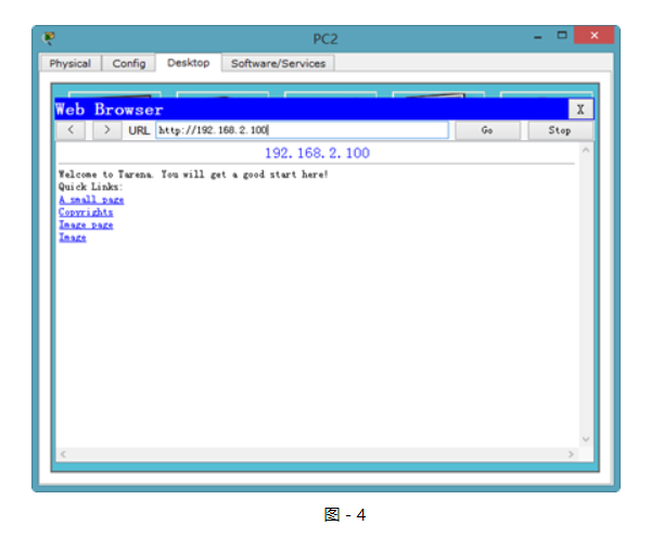
步驟二:在PC1和PC2上驗證到Web Server的HTTP協議訪問,如圖3和圖-4所示:
圖-3
?
圖-4
?
在沒有配置擴展ACL的時候,兩臺主機均可以正常訪問到Web Server。
步驟三:R1上配置擴展訪問控制列表,僅拒絕PC2到Web Server的HTTP訪問
擴展ACL可以對數據包中的源、目標IP地址以及端口號進行檢查,所以可以將該ACL放置在通信路徑中的任一位置。但是,如果放到離目標近的地方,每臺路由器都要對數據進行處理,會更多的消耗路由器和帶寬資源。放到離源最近的路由器端口入方向直接就將拒絕數據丟棄,可以減少其他路由器的資源占用以及帶寬占用。
- tarena-R1(config)#access-list 100 deny tcp host 192.168.0.20 host 192.168.2.100 eq www
- tarena-R1(config)#access-list 100 permit ip any any
- tarena-R1(config)#interface f0/0
- tarena-R1(config-if)#ip access-group 101 in
步驟四:在PC1上驗證
- PC>ipconfig
- FastEthernet0 Connection:(default port)
- Link-local IPv6 Address.........: FE80::2E0:F7FF:FED6:54CC
- IP Address......................: 192.168.0.10
- Subnet Mask.....................: 255.255.255.0
- Default Gateway.................: 192.168.0.1
- PC>ping 192.168.2.100
- Pinging 192.168.2.100 with 32 bytes of data:
- Reply from 192.168.2.100: bytes=32 time=1ms TTL=126
- Reply from 192.168.2.100: bytes=32 time=0ms TTL=126
- Reply from 192.168.2.100: bytes=32 time=0ms TTL=126
- Reply from 192.168.2.100: bytes=32 time=0ms TTL=126
- Ping statistics for 192.168.2.100:
- Packets: Sent = 4, Received = 4, Lost = 0 (0% loss),
- Approximate round trip times in milli-seconds:
- Minimum = 0ms, Maximum = 1ms, Average = 0ms
- PC>
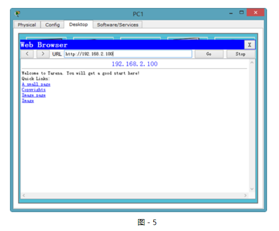
HTTP協議的驗證如圖-5所示:
圖-5
?
從輸入結果可以驗證,PC1到Web Server的訪問沒有受到任何影響。
步驟五:在PC2上進行驗證
- PC>ipconfig
- FastEthernet0 Connection:(default port)
- Link-local IPv6 Address.........: FE80::2D0:BAFF:FE98:9E29
- IP Address......................: 192.168.0.20
- Subnet Mask.....................: 255.255.255.0
- Default Gateway.................: 192.168.0.1
- PC>ping 192.168.2.100
- Pinging 192.168.2.100 with 32 bytes of data:
- Reply from 192.168.2.100: bytes=32 time=1ms TTL=126
- Reply from 192.168.2.100: bytes=32 time=1ms TTL=126
- Reply from 192.168.2.100: bytes=32 time=2ms TTL=126
- Reply from 192.168.2.100: bytes=32 time=0ms TTL=126
- Ping statistics for 192.168.2.100:
- Packets: Sent = 4, Received = 4, Lost = 0 (0% loss),
- Approximate round trip times in milli-seconds:
- Minimum = 0ms, Maximum = 2ms, Average = 1ms
- PC>
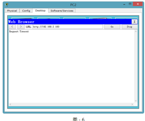
HTTP協議的驗證,如圖-6所示:
圖-6
?
因為只限制了到Web Server的HTTP訪問,所以WEB服務已經無法訪問,但是仍然可以ping通。
步驟六:在R1上查看相關的ACL信息
- tarena-R1#show ip access-lists
- Extended IP access list 100
- deny tcp host 192.168.0.20 host 192.168.2.100 eq www (30 match(es))
- permit ip any any (5 match(es))
路由器的輸出表明了拒絕了30個來自PC1到Web Server的HTTP訪問包。
3 配置標準命名ACL
3.1 問題
使用基本編號的ACL沒有實際意義,只有通過閱讀具體的條目才能得知該ACL的作用。而且ACL的編號有限制,如傳統的標準ACL用1~99表示,擴展ACL用100~199表示。
1)配置標準命名ACL實現拒絕PC2(IP地址為192.168.0.20)對Web Server的訪問
3.2 方案
命名訪問控制列表可以為ACL起一個有意義的名字,通過名稱就可以得知該ACL要實現什么功能。同時,因為使用的是名稱而不是數字,也就沒有了ACL數量上的限制。
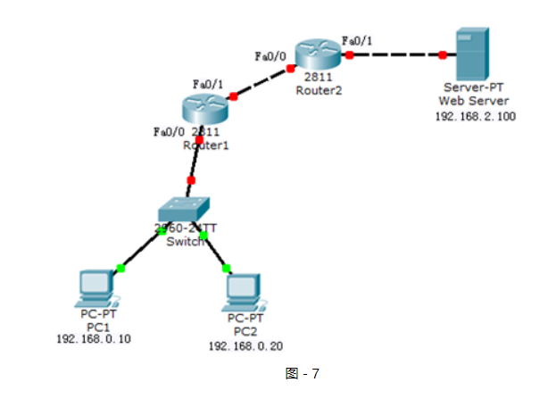
網絡拓撲如圖-7所示:
圖-7
?
3.3 步驟
實現此案例需要按照如下步驟進行。
步驟一:將2配置擴展ACL中的擴展訪問控制列表移除,其他配置保留
- tarena-R1(config)#interface f0/0
- tarena-R1(config-if)#no ip access-group 100 in
- tarena-R1(config-if)#exit
- tarena-R1(config)#no access-list 100
步驟二:在R2上配置標準的命名訪問控制列表
命名訪問控制列表的配置總體上和用數字表示的ACL一樣,但是更加靈活。
- tarena-R2(config)#ip access-list standard denypc2
- tarena-R2(config-std-nacl)#deny host 192.168.0.20
- tarena-R2(config-std-nacl)#permit any
- tarena-R2(config-std-nacl)#exit
- tarena-R2(config)#interface f0/1
- tarena-R2(config-if)#ip access-group denypc2 out
步驟三:分別在PC1和PC2上做連通性測試
PC1測試如下所示:
- PC>ipconfig
- FastEthernet0 Connection:(default port)
- Link-local IPv6 Address.........: FE80::2E0:F7FF:FED6:54CC
- IP Address......................: 192.168.0.10
- Subnet Mask.....................: 255.255.255.0
- Default Gateway.................: 192.168.0.1
- PC>ping 192.168.2.100
- Pinging 192.168.2.100 with 32 bytes of data:
- Reply from 192.168.2.100: bytes=32 time=0ms TTL=126
- Reply from 192.168.2.100: bytes=32 time=0ms TTL=126
- Reply from 192.168.2.100: bytes=32 time=0ms TTL=126
- Reply from 192.168.2.100: bytes=32 time=0ms TTL=126
- Ping statistics for 192.168.2.100:
- Packets: Sent = 4, Received = 4, Lost = 0 (0% loss),
- Approximate round trip times in milli-seconds:
- Minimum = 0ms, Maximum = 0ms, Average = 0ms
- PC>
PC2測試如下所示:
- PC>ipconfig
- FastEthernet0 Connection:(default port)
- Link-local IPv6 Address.........: FE80::2D0:BAFF:FE98:9E29
- IP Address......................: 192.168.0.20
- Subnet Mask.....................: 255.255.255.0
- Default Gateway.................: 192.168.0.1
- PC>ping 192.168.2.100
- Pinging 192.168.2.100 with 32 bytes of data:
- Reply from 192.168.1.2: Destination host unreachable.
- Reply from 192.168.1.2: Destination host unreachable.
- Reply from 192.168.1.2: Destination host unreachable.
- Reply from 192.168.1.2: Destination host unreachable.
- Ping statistics for 192.168.2.100:
- Packets: Sent = 4, Received = 0, Lost = 4 (100% loss),
- PC>
輸出結果表明,PC1的訪問是正常的,而PC2到Web Server的訪問被R2(IP地址為192.168.1.2)拒絕。
步驟四:在R2上查看相關的ACL信息
- tarena-R2#show ip access-lists
- Standard IP access list denypc2
- 10 deny host 192.168.0.20 (4 match(es))
- 20 permit any (4 match(es))
輸出結果也表明,來自于PC2的數據包被攔截。
4 配置擴展命名ACL
4.1 問題
使用基本編號的ACL沒有實際意義,只有通過閱讀具體的條目才能得知該ACL的作用。而且ACL的編號有限制,如傳統的標準ACL用1~99表示,擴展ACL用100~199表示。
1)配置擴展命名ACL實現拒絕PC2(IP地址為192.168.0.20)訪問Web Server Web服務,但可訪問其他服務。
4.2 方案
命名訪問控制列表可以為ACL起一個有意義的名字,通過名稱就可以得知該ACL要實現什么功能。同時,因為使用的是名稱而不是數字,也就沒有了ACL數量上的限制。
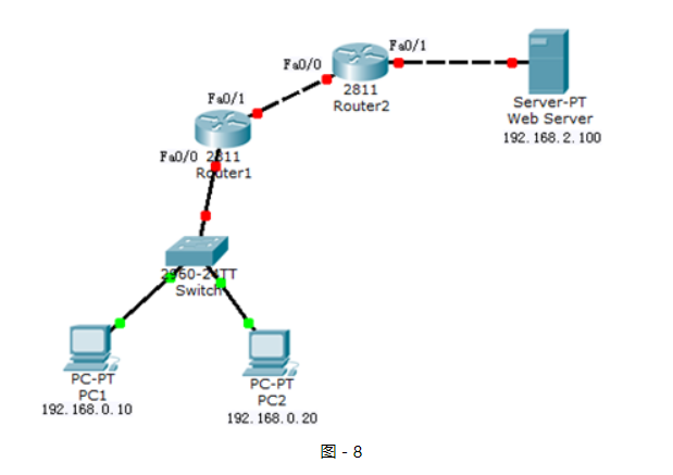
網絡拓撲如圖-8所示:
圖-8
?
4.3 步驟
實現此案例需要按照如下步驟進行。
步驟一:將3配置標準命名ACL中的標準命名訪問控制列表移除,其他配置保留
- tarena-R2(config)#interface f0/1
- tarena-R2(config-if)#no ip access-group denypc2 out
- tarena-R2(config-if)#exit
- tarena-R2(config)# no ip access-list standard denypc2
步驟二:在R2上配置擴展命名訪問控制列表
命名訪問控制列表的配置總體上和用數字表示的ACL一樣,但是更加靈活。
- tarena-R2(config)#ip access-list extended denypc2
- tarena-R2(config-ext-nacl)#deny tcp host 192.168.0.20 host 192.168.2.100 eq www
- tarena-R2(config-ext-nacl)#permit ip any any
- tarena-R2(config)#interface fastEthernet 0/1
- tarena-R2(config-if)#ip access-group denypc2 out
步驟三:在R2上查看相關的ACL信息
- tarena-R2#show access-lists
- Extended IP access list denypc2
- 10 deny tcp host 192.168.0.20 host 192.168.2.100 eq www
- 20 permit ip any any
步驟四:在PC1上驗證
- PC>ipconfig
- FastEthernet0 Connection:(default port)
- Link-local IPv6 Address.........: FE80::2E0:F7FF:FED6:54CC
- IP Address......................: 192.168.0.10
- Subnet Mask.....................: 255.255.255.0
- Default Gateway.................: 192.168.0.1
- PC>ping 192.168.2.100
- Pinging 192.168.2.100 with 32 bytes of data:
- Reply from 192.168.2.100: bytes=32 time=1ms TTL=126
- Reply from 192.168.2.100: bytes=32 time=0ms TTL=126
- Reply from 192.168.2.100: bytes=32 time=0ms TTL=126
- Reply from 192.168.2.100: bytes=32 time=0ms TTL=126
- Ping statistics for 192.168.2.100:
- Packets: Sent = 4, Received = 4, Lost = 0 (0% loss),
- Approximate round trip times in milli-seconds:
- Minimum = 0ms, Maximum = 1ms, Average = 0ms
- PC>
HTTP協議的驗證如圖-9所示:
圖-9
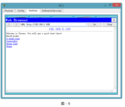
?
從輸入結果可以驗證,PC1到Web Server的訪問沒有受到任何影響。
步驟五:在PC2上進行驗證
- PC>ipconfig
- FastEthernet0 Connection:(default port)
- Link-local IPv6 Address.........: FE80::2D0:BAFF:FE98:9E29
- IP Address......................: 192.168.0.20
- Subnet Mask.....................: 255.255.255.0
- Default Gateway.................: 192.168.0.1
- PC>ping 192.168.2.100
- Pinging 192.168.2.100 with 32 bytes of data:
- Reply from 192.168.2.100: bytes=32 time=1ms TTL=126
- Reply from 192.168.2.100: bytes=32 time=1ms TTL=126
- Reply from 192.168.2.100: bytes=32 time=2ms TTL=126
- Reply from 192.168.2.100: bytes=32 time=0ms TTL=126
- Ping statistics for 192.168.2.100:
- Packets: Sent = 4, Received = 4, Lost = 0 (0% loss),
- Approximate round trip times in milli-seconds:
- Minimum = 0ms, Maximum = 2ms, Average = 1ms
- PC>
HTTP協議的驗證,如圖-10所示:
圖-10
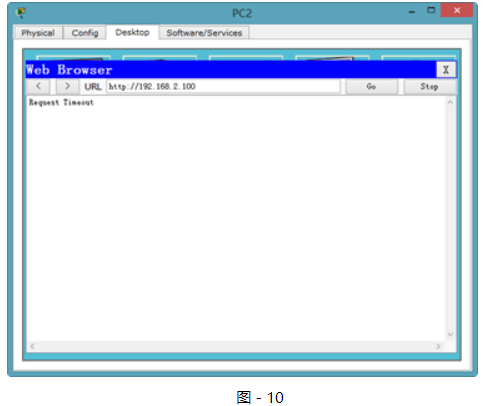
?
因為只限制了到Web Server的HTTP訪問,所以WEB服務已經無法訪問,但是仍然可以ping通。


)


