關于Unity的Shader部分的基礎知識其實已經講解得差不多了,今天我們來一些實例分享:
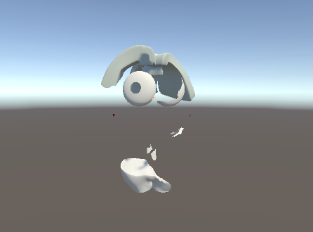
溶解
效果如下:
代碼如下:
Shader "Chapter8/chapter8_1"
{Properties{// 定義屬性[NoScaleOffset]_Albedo("Albedo", 2D) = "white" {} // 基礎顏色紋理,默認白色_Noise("Dissolve Noise", 2D) = "white" {} // 溶解噪聲紋理,默認白色_Dissolve("Dissolve", Range(0, 1)) = 0 // 溶解程度,范圍0到1,默認0[NoScaleOffset]_Gradient("Edge Gradient", 2D) = "black" {} // 邊緣漸變紋理,默認黑色_Range("Edge Range", Range(2, 100)) = 6 // 邊緣范圍,范圍2到100,默認6_Brightness("Brightness", Range(0, 10)) = 1 // 亮度,范圍0到10,默認1}SubShader{Tags{ "RenderType"="TransparentCutout" "Queue" = "AlphaTest" // 渲染類型為透明剪切,隊列為Alpha測試}CGPROGRAM#pragma surface surf StandardSpecular addshadow fullforwardshadows // 使用StandardSpecular表面著色器,并添加陰影和全向陰影struct Input{float2 uv_Albedo; // Albedo紋理的UV坐標float2 uv_Noise; // 噪聲紋理的UV坐標};sampler2D _Albedo; // Albedo紋理sampler2D _Noise; // 噪聲紋理fixed _Dissolve; // 溶解程度sampler2D _Gradient; // 邊緣漸變紋理float _Range; // 邊緣范圍float _Brightness; // 亮度void surf (Input IN, inout SurfaceOutputStandardSpecular o){// 溶解遮罩fixed noise = tex2D(_Noise, IN.uv_Noise).r; // 從噪聲紋理中獲取紅色通道值fixed dissolve = _Dissolve * 2 - 1; // 將溶解程度從0-1映射到-1到1fixed mask = saturate(noise - dissolve); // 計算遮罩值,限制在0到1之間clip(mask - 0.5); // 根據遮罩值進行剪切,小于0.5的部分將被剔除// 燃燒效果fixed texcoord = saturate(mask * _Range - 0.5 * _Range); // 計算紋理坐標,用于邊緣漸變o.Emission = tex2D(_Gradient, fixed2(texcoord, 0.5)) * _Brightness; // 根據漸變紋理和亮度計算自發光fixed4 c = tex2D (_Albedo, IN.uv_Albedo); // 從Albedo紋理中獲取顏色o.Albedo = c.rgb; // 設置表面顏色}ENDCG}
}
屬性中有一個[NoScaleOffset]:
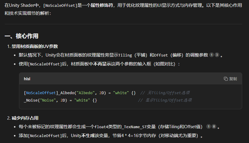 一言以蔽之,?[NoScaleOffset]修飾的紋理的尺寸不可修改(至少在Inspector界面不可修改)。
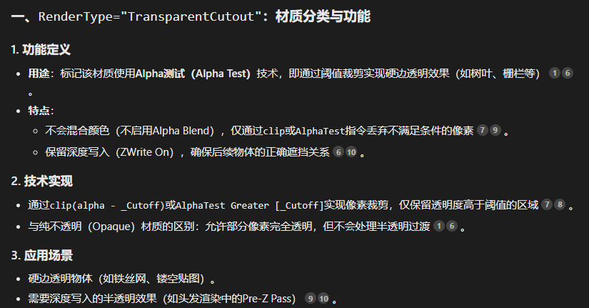
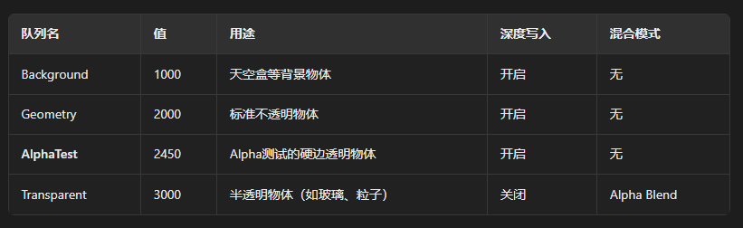
Tags{ "RenderType"="TransparentCutout" "Queue" = "AlphaTest" // 渲染類型為透明剪切,隊列為Alpha測試}Tags中設置渲染類型為TransparentCutout而渲染隊列為AlphaTest。
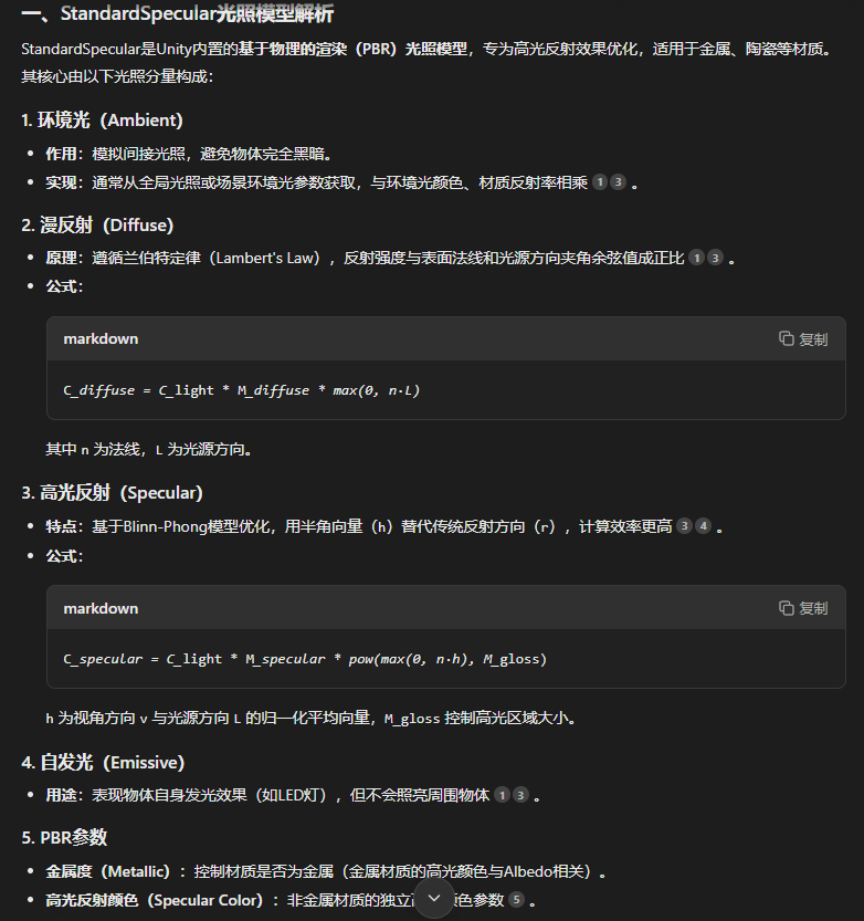
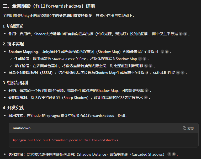
#pragma surface surf StandardSpecular addshadow fullforwardshadows // 使用StandardSpecular表面著色器,并添加陰影和全向陰影正如注釋所寫,使用表面著色器,相關函數為surf,采用StandardSpecular光照模型,添加陰影以及全向陰影。
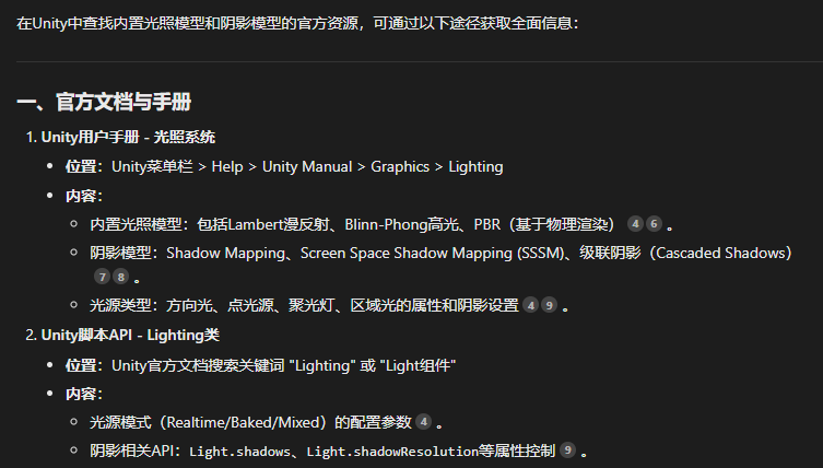
如果我們需要去查詢Unity內置的光照模型和陰影模型可以:
struct Input{float2 uv_Albedo; // Albedo紋理的UV坐標float2 uv_Noise; // 噪聲紋理的UV坐標};?這是作為輸入的結構體,內部包含的是基礎的紋理的UV坐標和噪聲紋理的UV紋理。
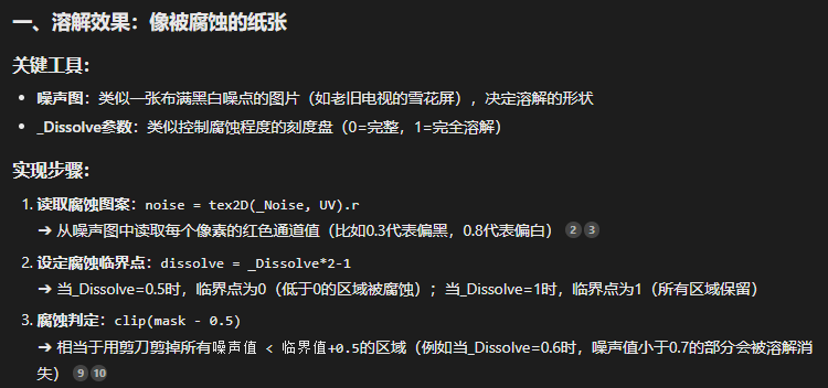
void surf (Input IN, inout SurfaceOutputStandardSpecular o){// 溶解遮罩fixed noise = tex2D(_Noise, IN.uv_Noise).r; // 從噪聲紋理中獲取紅色通道值fixed dissolve = _Dissolve * 2 - 1; // 將溶解程度從0-1映射到-1到1fixed mask = saturate(noise - dissolve); // 計算遮罩值,限制在0到1之間clip(mask - 0.5); // 根據遮罩值進行剪切,小于0.5的部分將被剔除// 燃燒效果fixed texcoord = saturate(mask * _Range - 0.5 * _Range); // 計算紋理坐標,用于邊緣漸變o.Emission = tex2D(_Gradient, fixed2(texcoord, 0.5)) * _Brightness; // 根據漸變紋理和亮度計算自發光fixed4 c = tex2D (_Albedo, IN.uv_Albedo); // 從Albedo紋理中獲取顏色o.Albedo = c.rgb; // 設置表面顏色}我們實現了兩個效果:溶解的遮罩,我們獲取噪聲紋理的紅色通道值之后減去溶解的程度值來作為遮罩值,遮罩值小于0.5的部分將會被剔除。
然后是邊緣的燃燒效果,我們利用之前生成的遮罩值來計算紋理坐標之后再根據紋理坐標來乘以自發光強度實現漸變紋理。最后我們從基礎紋理中獲取顏色后再添加到輸出的模型中。
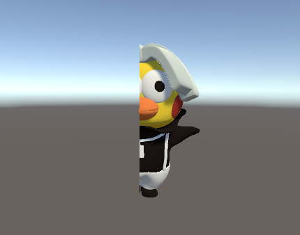
透視
效果如圖:
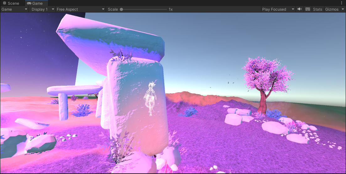
能夠看到我們可以透過巖石看到人物的輪廓。
代碼如下:
Shader "Chapter8/chapter8_2"
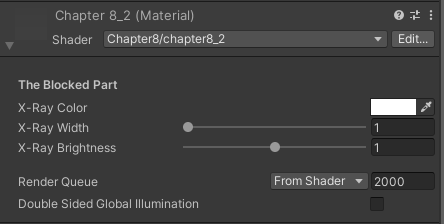
{Properties{// 定義屬性[Header(The Blocked Part)] // 標題,表示以下屬性是用于被遮擋部分的設置[Space(10)] // 在Inspector中留出10像素的空白_Color ("X-Ray Color", Color) = (0,1,1,1) // X射線顏色,默認青色_Width ("X-Ray Width", Range(1, 2)) = 1 // X射線寬度,范圍1到2,默認1_Brightness ("X-Ray Brightness",Range(0, 2)) = 1 // X射線亮度,范圍0到2,默認1}SubShader{Tags{"RenderType" = "Opaque" "Queue" = "Geometry"} // 渲染類型為不透明,隊列為幾何體//---------- 被遮擋部分的效果 ----------Pass{ZTest Greater // 深度測試設置為大于當前深度值時才渲染(即渲染被遮擋的部分)ZWrite Off // 關閉深度寫入,避免影響后續渲染Blend SrcAlpha OneMinusSrcAlpha // 設置混合模式,實現透明效果CGPROGRAM#pragma vertex vert // 頂點著色器#pragma fragment frag // 片段著色器#include "UnityCG.cginc" // 引入Unity的CG庫// 定義頂點著色器的輸出結構struct v2f{float4 vertexPos : SV_POSITION; // 頂點在裁剪空間中的位置float3 viewDir : TEXCOORD0; // 視線方向float3 worldNor : TEXCOORD1; // 世界空間中的法線方向};// 頂點著色器v2f vert(appdata_base v){v2f o;o.vertexPos = UnityObjectToClipPos(v.vertex); // 將頂點從對象空間轉換到裁剪空間o.viewDir = normalize(WorldSpaceViewDir(v.vertex)); // 計算視線方向o.worldNor = UnityObjectToWorldNormal(v.normal); // 將法線從對象空間轉換到世界空間return o;}// 聲明屬性變量fixed4 _Color; // X射線顏色fixed _Width; // X射線寬度half _Brightness; // X射線亮度// 片段著色器float4 frag(v2f i) : SV_Target{//計算邊緣光強度half NDotV = saturate(dot(i.worldNor, i.viewDir)); // 計算法線與視線方向的點積NDotV = pow(1 - NDotV, _Width) * _Brightness; // 根據寬度和亮度調整邊緣光強度fixed4 color;color.rgb = _Color.rgb; // 設置顏色color.a = NDotV; // 設置透明度(基于Fresnel值)return color; // 返回最終顏色}ENDCG}}
} // 定義屬性[Header(The Blocked Part)] // 標題,表示以下屬性是用于被遮擋部分的設置[Space(10)] // 在Inspector中留出10像素的空白_Color ("X-Ray Color", Color) = (0,1,1,1) // X射線顏色,默認青色_Width ("X-Ray Width", Range(1, 2)) = 1 // X射線寬度,范圍1到2,默認1_Brightness ("X-Ray Brightness",Range(0, 2)) = 1 // X射線亮度,范圍0到2,默認1首先是屬性中,[Space(10)]在Inspector中留出10像素的空白,效果如圖。
Tags{"RenderType" = "Opaque" "Queue" = "Geometry"}Tags中渲染類型為不透明,隊列為幾何體。
ZTest Greater // 深度測試設置為大于當前深度值時才渲染(即渲染被遮擋的部分)ZWrite Off // 關閉深度寫入,避免影響后續渲染
開啟深度測試的同時關閉深度寫入。
// 定義頂點著色器的輸出結構struct v2f{float4 vertexPos : SV_POSITION; // 頂點在裁剪空間中的位置float3 viewDir : TEXCOORD0; // 視線方向float3 worldNor : TEXCOORD1; // 世界空間中的法線方向};頂點著色器的輸出中多了一個視線方向。
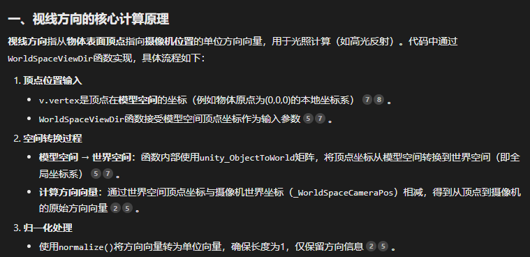
// 頂點著色器v2f vert(appdata_base v){v2f o;o.vertexPos = UnityObjectToClipPos(v.vertex); // 將頂點從對象空間轉換到裁剪空間o.viewDir = normalize(WorldSpaceViewDir(v.vertex)); // 計算視線方向o.worldNor = UnityObjectToWorldNormal(v.normal); // 將法線從對象空間轉換到世界空間return o;}這里的視線方向計算方法:
最后是片元著色器的內容:
// 片段著色器float4 frag(v2f i) : SV_Target{//計算邊緣光強度half NDotV = saturate(dot(i.worldNor, i.viewDir)); // 計算法線與視線方向的點積NDotV = pow(1 - NDotV, _Width) * _Brightness; // 根據寬度和亮度調整邊緣光強度fixed4 color;color.rgb = _Color.rgb; // 設置顏色color.a = NDotV; // 設置透明度(基于Fresnel值)return color; // 返回最終顏色}?這里的邊緣光強度計算的內容可能比較難以理解,我們先用法線和視線方向進行一個點積之后調整該值到[0,1]之間,然后根據寬度和亮度來調整光強,這里我們采用了冪次計算,寬度作為冪,那么寬度值越小則光強越小,同時注意我們的base是一減去點積,意思就是法線和視線的夾角越大則光強越強(夾角越大則越邊緣),我們通過這些函數實現了邊緣光越邊緣強度越大的效果。
切割
效果如圖:
非常直接的切割效果,代碼如下:
Shader "Chapter8/chapter8_3"
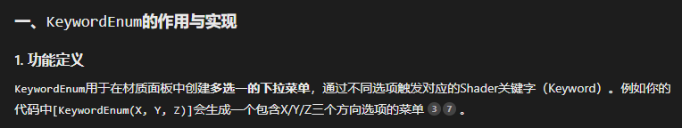
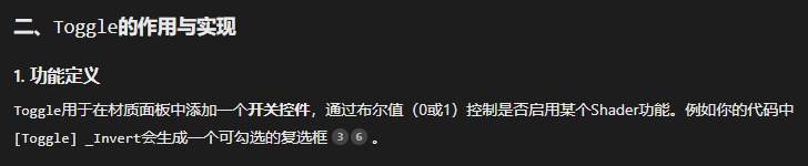
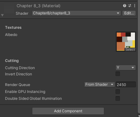
{Properties{// 紋理部分[Header(Textures)] [Space(10)] // 標題和空白[NoScaleOffset] _Albedo ("Albedo", 2D) = "white" {} // 基礎顏色紋理,默認白色,無縮放偏移// 切割部分[Header(Cutting)] [Space(10)] // 標題和空白[KeywordEnum(X, Y, Z)] _Direction ("Cutting Direction", Float) = 1 // 切割方向枚舉(X、Y、Z),默認Y軸[Toggle] _Invert ("Invert Direction", Float) = 0 // 是否反轉切割方向,默認關閉}SubShader{Tags { "RenderType"="TransparentCutout" "Queue"="AlphaTest" } // 渲染類型為透明剪切,隊列為Alpha測試Cull Off // 關閉背面剔除,渲染雙面CGPROGRAM#pragma surface surf StandardSpecular addshadow fullforwardshadows // 使用StandardSpecular表面著色器,添加陰影和全向陰影#pragma target 3.0 // 目標著色器模型3.0#pragma multi_compile _DIRECTION_X _DIRECTION_Y _DIRECTION_Z // 多編譯選項,支持X、Y、Z三個方向的切割sampler2D _Albedo; // 基礎顏色紋理float3 _Position; // 切割位置fixed _Invert; // 是否反轉切割方向struct Input{float2 uv_Albedo; // 基礎顏色紋理的UV坐標float3 worldPos; // 世界空間中的頂點位置fixed face : VFACE; // 判斷當前渲染的是正面還是背面};void surf (Input i, inout SurfaceOutputStandardSpecular o){// 獲取基礎顏色fixed4 col = tex2D(_Albedo, i.uv_Albedo);// 如果是正面,使用紋理顏色;如果是背面,使用黑色o.Albedo = i.face > 0 ? col.rgb : fixed3(0,0,0);// 判斷切割方向#if _DIRECTION_X// 如果選擇X軸方向,根據世界坐標的X值與切割位置比較col.a = step(_Position.x, i.worldPos.x);#elif _DIRECTION_Y// 如果選擇Y軸方向,根據世界坐標的Y值與切割位置比較col.a = step(_Position.y, i.worldPos.y);#else // 如果選擇Z軸方向,根據世界坐標的Z值與切割位置比較col.a = step(_Position.z, i.worldPos.z);#endif// 判斷是否反轉切割方向col.a = _Invert? 1 - col.a : col.a;// 根據透明度進行剪切,小于0.001的部分將被剔除clip(col.a - 0.001);}ENDCG}
} {// 紋理部分[Header(Textures)] [Space(10)] // 標題和空白[NoScaleOffset] _Albedo ("Albedo", 2D) = "white" {} // 基礎顏色紋理,默認白色,無縮放偏移// 切割部分[Header(Cutting)] [Space(10)] // 標題和空白[KeywordEnum(X, Y, Z)] _Direction ("Cutting Direction", Float) = 1 // 切割方向枚舉(X、Y、Z),默認Y軸[Toggle] _Invert ("Invert Direction", Float) = 0 // 是否反轉切割方向,默認關閉}?這里有兩個新東西:KeywordEnum和一個Toggle。
效果如下:
struct Input{float2 uv_Albedo; // 基礎顏色紋理的UV坐標float3 worldPos; // 世界空間中的頂點位置fixed face : VFACE; // 判斷當前渲染的是正面還是背面};作為輸入的結構體里除了基本的紋理UV坐標和頂點坐標以外還有一個聲明為VFACE的face變量,用來表明具體渲染的是正面還是背面。
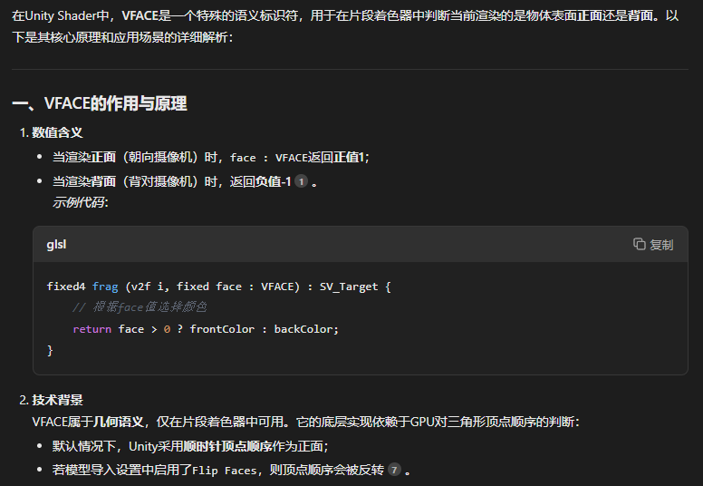
void surf (Input i, inout SurfaceOutputStandardSpecular o){// 獲取基礎顏色fixed4 col = tex2D(_Albedo, i.uv_Albedo);// 如果是正面,使用紋理顏色;如果是背面,使用黑色o.Albedo = i.face > 0 ? col.rgb : fixed3(0,0,0);// 判斷切割方向#if _DIRECTION_X// 如果選擇X軸方向,根據世界坐標的X值與切割位置比較col.a = step(_Position.x, i.worldPos.x);#elif _DIRECTION_Y// 如果選擇Y軸方向,根據世界坐標的Y值與切割位置比較col.a = step(_Position.y, i.worldPos.y);#else // 如果選擇Z軸方向,根據世界坐標的Z值與切割位置比較col.a = step(_Position.z, i.worldPos.z);#endif// 判斷是否反轉切割方向col.a = _Invert? 1 - col.a : col.a;// 根據透明度進行剪切,小于0.001的部分將被剔除clip(col.a - 0.001);}表面著色器里,我們首先獲取紋理的顏色,然后先判斷是正面還是背面,接著從X,Y,Z軸選擇切割的方向,根據選擇的軸來確定世界坐標和切割位置的比較。這里我們使用了一個函數step來進行比較,step的具體用法如下:
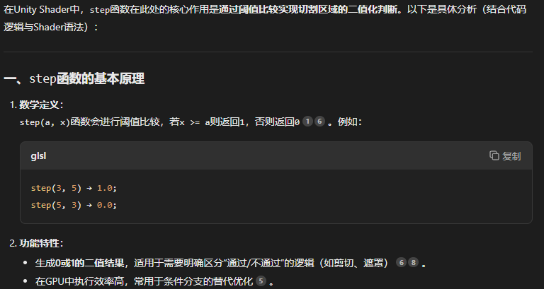
最后把小于閾值的部分直接剔除掉即可。
切割軸為Y軸時效果如圖:
廣告
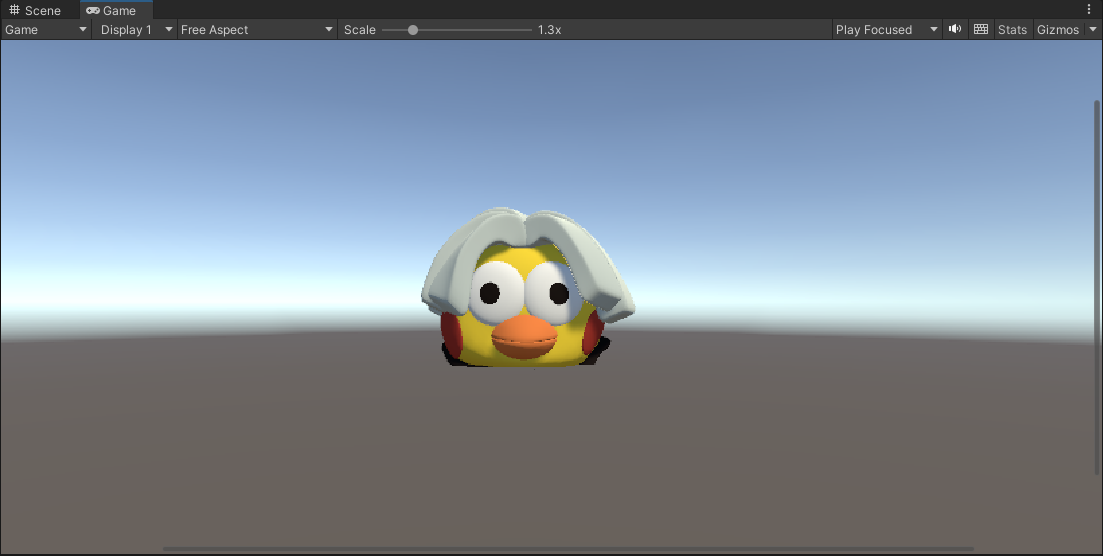
效果如下:
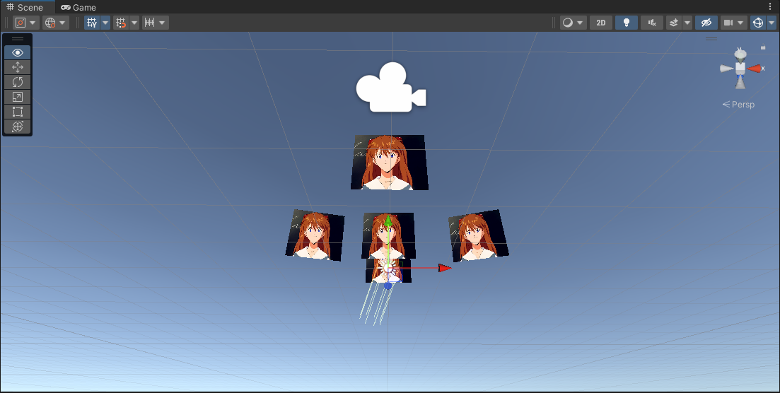
就是實現無論哪個位置看到的圖片效果都一樣。
代碼如下:
Shader "Chapter8/chapter8_4"
{Properties{[NoScaleOffset] _Tex ("Texture", 2D) = "white" {}[KeywordEnum(Spherical, Cylindrical)] _Type ("Type", float) = 0}SubShader{Tags{"RenderType" = "Transparent""Queue" = "Transparent""DisableBatching" = "True"}//Blend OneMinusDstColor OneZWrite OffPass{CGPROGRAM#pragma vertex vert#pragma fragment frag// 聲明枚舉的關鍵詞#pragma shader_feature _TYPE_SPHERICAL _TYPE_CYLINDRICALstruct appdata{float4 vertex : POSITION;float2 texcoord : TEXCOORD0;};struct v2f{float4 vertex : SV_POSITION;float2 texcoord : TEXCOORD0;};sampler2D _Tex;v2f vert (appdata v){v2f o;// 計算面片朝向攝像機的前方向量float3 forward = mul(unity_WorldToObject,float4(_WorldSpaceCameraPos, 1)).xyz;// 判斷Billboard的類型#if _TYPE_CYLINDRICALforward.y = 0;#endifforward = normalize(forward);// 當攝像機完全在面片正上方或者正下方的時候,旋轉臨時的上方向量float3 up = abs(forward.y) > 0.999 ? float3(0, 0, 1) : float3(0, 1, 0);float3 right = normalize(cross(forward, up));up = normalize(cross(right, forward));// 將頂點在新的坐標系上移動位置float3 vertex = v.vertex.x * right + v.vertex.y * up;o.vertex = UnityObjectToClipPos(vertex);o.texcoord = v.texcoord;return o;}float4 frag (v2f i) : SV_Target{return tex2D(_Tex, i.texcoord);}ENDCG}}
}
Tags{"RenderType" = "Transparent""Queue" = "Transparent""DisableBatching" = "True"}這次的Tags里有新東西DisableBatching:
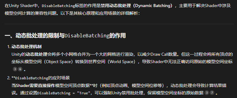
總結來說就是,批處理可以減少draw call但是會導致頂點坐標從模型空間轉換為世界空間,所以如果在后續的代碼中我們要使用模型空間的坐標的話就無法使用,所以我們需要顯式地禁止使用批處理。
// 聲明枚舉的關鍵詞#pragma shader_feature _TYPE_SPHERICAL _TYPE_CYLINDRICAL比起往常的shader多了一個shader_feature。
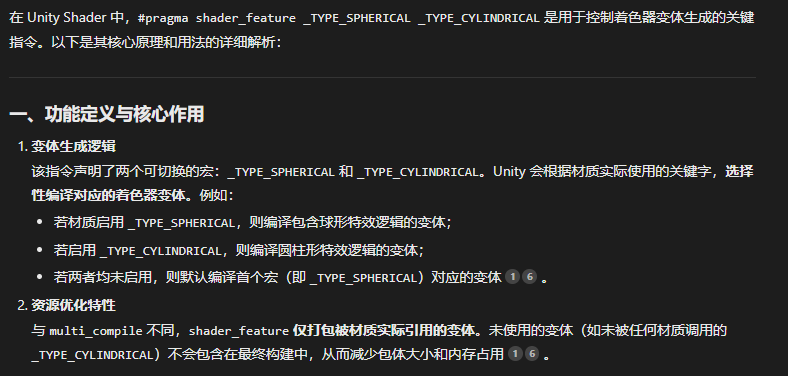
shader_feature本質上更像一個shader代碼里的宏定義,我們可以根據不同的宏定義替換不同的shader變體。?
v2f vert (appdata v){v2f o;// 計算面片朝向攝像機的前方向量float3 forward = mul(unity_WorldToObject,float4(_WorldSpaceCameraPos, 1)).xyz;// 判斷Billboard的類型#if _TYPE_CYLINDRICALforward.y = 0;#endifforward = normalize(forward);// 當攝像機完全在面片正上方或者正下方的時候,旋轉臨時的上方向量float3 up = abs(forward.y) > 0.999 ? float3(0, 0, 1) : float3(0, 1, 0);float3 right = normalize(cross(forward, up));up = normalize(cross(right, forward));// 將頂點在新的坐標系上移動位置float3 vertex = v.vertex.x * right + v.vertex.y * up;o.vertex = UnityObjectToClipPos(vertex);o.texcoord = v.texcoord;return o;}我們將攝像機的世界空間坐標從世界坐標系轉換到模型空間坐標系,獲得該面片朝向攝像機的方向向量。如果是圓柱形的廣告牌,我們將這個方向向量的y軸修改為0。否則如果該方向向量的y軸分量大于0.999(基本就是在純上方)我們把向上的向量直接設置為z軸方向向量(此時forward向量和向上向量高度重合,叉乘大概率為0,后續計算無法展開),否則就設置為y軸方向向量,然后用前向向量和上方向量叉乘得到右側向量,之后再用右向向量和前方向量叉乘得到上方向量。
最后我們把v的頂點坐標和紋理坐標都根據這個右向向量和上方向量更新之后即可,這樣我們就實現了一個面片永遠朝向攝像機的效果。
扭曲
效果如下:
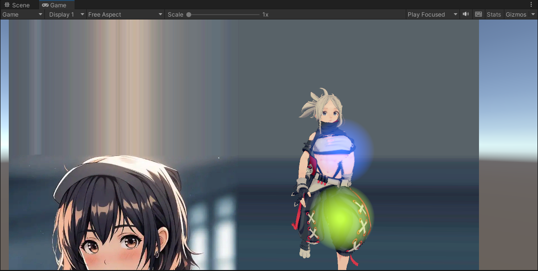
可以看到這些形形色色的顏色球在的位置視線被扭曲了。
代碼如下:
Shader "Chapter8/chapter8_5"
{Properties{_StrengthColor("Color strength", Float) = 1 // 顏色強度,默認1_DistortionStrength ("Distortion strength", Range(-2,2)) = 0.1 // 扭曲強度,范圍-2到2,默認0.1_DistortionCircle ("Distortion circle", Range(0,1)) = 0 // 扭曲圓形范圍,范圍0到1,默認0_NormalTexture("Normal", 2D) = "blue" { } // 法線紋理,默認藍色_NormalTexStrength("Normal strength", Range(0,1)) = 0.5 // 法線強度,范圍0到1,默認0.5_NormalTexFrameless("Normal circle", Range(0,1)) = 0.5 // 法線圓形范圍,范圍0到1,默認0.5_UVOffset("UVOffset XY, ignore ZW", Vector) = (0,0.01,0,0) // UV偏移,默認(0, 0.01, 0, 0)}Category{Tags { "Queue" = "Transparent" "RenderType" = "Transparent" "IgnoreProjector" = "True" } // 渲染隊列為透明,渲染類型為透明,忽略投影器Blend SrcAlpha OneMinusSrcAlpha // 混合模式:SrcAlpha, OneMinusSrcAlphaZWrite Off // 關閉深度寫入SubShader{GrabPass // 抓取屏幕內容{Name "BASE"Tags { "LightMode" = "Always" }}Pass{Name "BASE"Tags { "LightMode" = "Always" }CGPROGRAM#pragma vertex vert // 頂點著色器#pragma fragment frag // 片段著色器#include "UnityCG.cginc" // 引入Unity的CG庫sampler2D _GrabTexture; // 抓取的屏幕紋理float _DistortionStrength; // 扭曲強度float _DistortionCircle; // 扭曲圓形范圍float _StrengthColor; // 顏色強度sampler2D _NormalTexture; // 法線紋理float4 _NormalTexture_ST; // 法線紋理的縮放和偏移float _NormalTexStrength; // 法線強度float _NormalTexFrameless; // 法線圓形范圍float4 _UVOffset; // UV偏移// 頂點著色器輸入結構struct VertexInput{float4 vertex : POSITION; // 頂點位置float2 texcoord0 : TEXCOORD0; // 紋理坐標float4 color : COLOR; // 頂點顏色};// 頂點著色器輸出結構struct Vert2Frag{float4 position : SV_POSITION; // 裁剪空間中的頂點位置float4 uv_grab : TEXCOORD0; // 抓取紋理的UV坐標float2 uv : TEXCOORD1; // 紋理坐標float2 uv_normal : TEXCOORD2; // 法線紋理的UV坐標float2 movement: TEXCOORD3; // UV偏移運動float4 color : TEXCOORD4; // 頂點顏色};// 頂點著色器Vert2Frag vert (VertexInput vertIn){Vert2Frag output;output.position = UnityObjectToClipPos(vertIn.vertex); // 將頂點從對象空間轉換到裁剪空間output.uv_grab = ComputeGrabScreenPos(output.position); // 計算抓取紋理的UV坐標output.uv = vertIn.texcoord0; // 傳遞紋理坐標output.uv_normal = vertIn.texcoord0.xy * _NormalTexture_ST.xy + _NormalTexture_ST.zw; // 計算法線紋理的UV坐標output.movement = _UVOffset.xy*_Time.y; // 計算UV偏移運動output.color = vertIn.color; // 傳遞頂點顏色return output;}// 獲取從中心到當前UV的向量float2 getVectorFromCenter(float2 uv){float factor = _ScreenParams.y / _ScreenParams.x; // 計算屏幕寬高比float2 direction = float2((uv.x-0.5), (uv.y-0.5)) * factor; // 計算從中心到當前UV的向量return (direction);}// 獲取扭曲強度float getDistortionStrength(float2 uv){float2 diff = float2(distance(0.5, uv.x), distance(0.5, uv.y)) * 2.0; // 計算UV到中心的距離float dist = saturate(length(diff)); // 計算距離并限制在0到1之間return 1.0-dist; // 返回扭曲強度}// 獲取法線float2 getNormal(sampler2D _NormalTexture, float2 normalUv, float2 uv, float2 uvOffset, float frameless, float strength){float2 normal = tex2D( _NormalTexture, normalUv+uvOffset ).zy; // 從法線紋理中獲取法線值float length = getDistortionStrength(uv); // 獲取扭曲強度float normalTexStrength = ((1-frameless) + frameless*length) * strength; // 計算法線強度normal.x = ((normal.x-.5)*2) * normalTexStrength; // 調整法線X分量normal.y = ((normal.y-.5)*2) * normalTexStrength; // 調整法線Y分量return normal; // 返回法線}// 片段著色器half4 frag (Vert2Frag fragIn) : SV_Target{float4 uvScreen = UNITY_PROJ_COORD(fragIn.uv_grab); // 獲取抓取紋理的UV坐標float2 direction = getVectorFromCenter(fragIn.uv); // 獲取從中心到當前UV的向量float strength = getDistortionStrength(fragIn.uv); // 獲取扭曲強度strength = (_DistortionCircle*strength + (1-_DistortionCircle)) * _DistortionStrength; // 計算最終扭曲強度direction *= strength; // 調整方向向量uvScreen += float4(direction.x, direction.y, 0, 0); // 調整抓取紋理的UV坐標float2 influence = normalize(direction) * strength; // 計算影響向量float2 offset = fragIn.movement; // 獲取UV偏移float2 normal = getNormal(_NormalTexture, fragIn.uv_normal, fragIn.uv, offset, _NormalTexFrameless, _NormalTexStrength); // 獲取法線uvScreen += float4(normal.x, normal.y, 0, 0); // 調整抓取紋理的UV坐標influence += normal.xy; // 調整影響向量float4 final = tex2Dproj(_GrabTexture, uvScreen); // 從抓取紋理中獲取顏色float alpha = 1; // 設置透明度final = float4(final.xyz, alpha); // 設置最終顏色strength = saturate(sqrt(pow(abs(influence.x), 2.0) + pow(abs(influence.y), 2.0)) * _StrengthColor); // 計算最終強度final = final + (fragIn.color*strength); // 調整最終顏色final.w = saturate(final.w*fragIn.color.w); // 調整最終透明度return final; // 返回最終顏色}ENDCG}}}
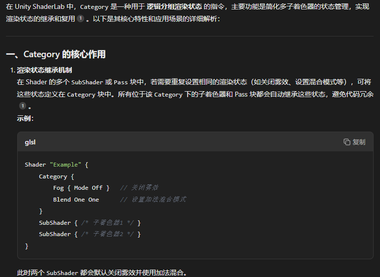
}我們應該首先能發現這一次的shader中沒有Pass而是Category:
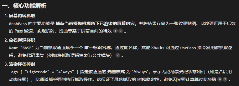
GrabPass // 抓取屏幕內容{Name "BASE"Tags { "LightMode" = "Always" }}如果還記得我們透明章節的話,我們在那里介紹過GrabPass:從屏幕中抓取緩沖來使用。
// 頂點著色器輸入結構struct VertexInput{float4 vertex : POSITION; // 頂點位置float2 texcoord0 : TEXCOORD0; // 紋理坐標float4 color : COLOR; // 頂點顏色};// 頂點著色器輸出結構struct Vert2Frag{float4 position : SV_POSITION; // 裁剪空間中的頂點位置float4 uv_grab : TEXCOORD0; // 抓取紋理的UV坐標float2 uv : TEXCOORD1; // 紋理坐標float2 uv_normal : TEXCOORD2; // 法線紋理的UV坐標float2 movement: TEXCOORD3; // UV偏移運動float4 color : TEXCOORD4; // 頂點顏色};?頂點著色器的輸入和輸出都有很多東西,把頂點位置、紋理坐標和頂點顏色作為輸入而輸出裁剪空間的頂點位置、抓取的紋理坐標、紋理坐標、法線紋理坐標、UV的偏移和顏色。
// 頂點著色器Vert2Frag vert (VertexInput vertIn){Vert2Frag output;output.position = UnityObjectToClipPos(vertIn.vertex); // 將頂點從對象空間轉換到裁剪空間output.uv_grab = ComputeGrabScreenPos(output.position); // 計算抓取紋理的UV坐標output.uv = vertIn.texcoord0; // 傳遞紋理坐標output.uv_normal = vertIn.texcoord0.xy * _NormalTexture_ST.xy + _NormalTexture_ST.zw; // 計算法線紋理的UV坐標output.movement = _UVOffset.xy*_Time.y; // 計算UV偏移運動output.color = vertIn.color; // 傳遞頂點顏色return output;}這是頂點著色器的函數代碼內容。
// 獲取從中心到當前UV的向量float2 getVectorFromCenter(float2 uv){float factor = _ScreenParams.y / _ScreenParams.x; // 計算屏幕寬高比float2 direction = float2((uv.x-0.5), (uv.y-0.5)) * factor; // 計算從中心到當前UV的向量return (direction);}// 獲取扭曲強度float getDistortionStrength(float2 uv){float2 diff = float2(distance(0.5, uv.x), distance(0.5, uv.y)) * 2.0; // 計算UV到中心的距離float dist = saturate(length(diff)); // 計算距離并限制在0到1之間return 1.0-dist; // 返回扭曲強度}// 獲取法線float2 getNormal(sampler2D _NormalTexture, float2 normalUv, float2 uv, float2 uvOffset, float frameless, float strength){float2 normal = tex2D( _NormalTexture, normalUv+uvOffset ).zy; // 從法線紋理中獲取法線值float length = getDistortionStrength(uv); // 獲取扭曲強度float normalTexStrength = ((1-frameless) + frameless*length) * strength; // 計算法線強度normal.x = ((normal.x-.5)*2) * normalTexStrength; // 調整法線X分量normal.y = ((normal.y-.5)*2) * normalTexStrength; // 調整法線Y分量return normal; // 返回法線}這里有三個函數,分別用于計算從中心到當前UV的向量,計算扭曲強度以及獲取法線。
第一個函數,我們首先計算一個屏幕的高寬比,然后把uv的x軸和y軸各減去0.5之后乘以這個比值,因為我們知道uv坐標是一個從0到1的坐標系,所以這樣能得到正確的向量。
第二個函數中,我們先計算uv坐標的xy坐標到屏幕的中心的距離,然后把這個距離限制在[0,1]之間,最后返回一減去這個距離即可。
第三個函數中,我們首先從法線紋理中獲取到法線,然后使用第二個函數獲取扭曲強度,然后我們根據扭曲強度和參數中的邊緣衰減(frameless)來動態調整法線強度。
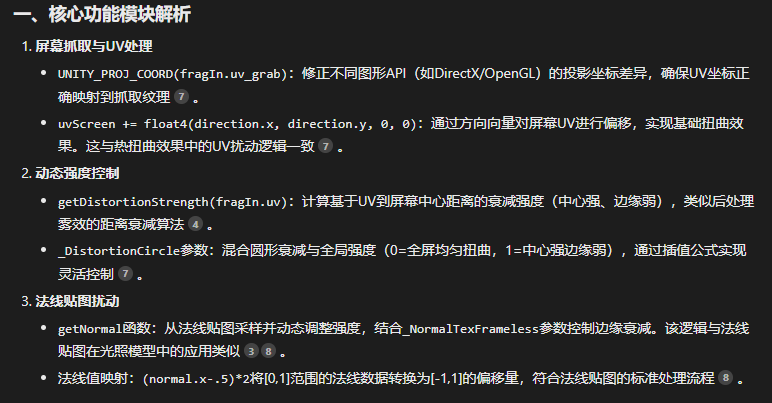
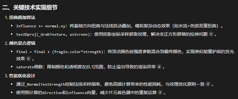
// 片段著色器half4 frag (Vert2Frag fragIn) : SV_Target{float4 uvScreen = UNITY_PROJ_COORD(fragIn.uv_grab); // 獲取抓取紋理的UV坐標float2 direction = getVectorFromCenter(fragIn.uv); // 獲取從中心到當前UV的向量float strength = getDistortionStrength(fragIn.uv); // 獲取扭曲強度strength = (_DistortionCircle*strength + (1-_DistortionCircle)) * _DistortionStrength; // 計算最終扭曲強度direction *= strength; // 調整方向向量uvScreen += float4(direction.x, direction.y, 0, 0); // 調整抓取紋理的UV坐標float2 influence = normalize(direction) * strength; // 計算影響向量float2 offset = fragIn.movement; // 獲取UV偏移float2 normal = getNormal(_NormalTexture, fragIn.uv_normal, fragIn.uv, offset, _NormalTexFrameless, _NormalTexStrength); // 獲取法線uvScreen += float4(normal.x, normal.y, 0, 0); // 調整抓取紋理的UV坐標influence += normal.xy; // 調整影響向量float4 final = tex2Dproj(_GrabTexture, uvScreen); // 從抓取紋理中獲取顏色float alpha = 1; // 設置透明度final = float4(final.xyz, alpha); // 設置最終顏色strength = saturate(sqrt(pow(abs(influence.x), 2.0) + pow(abs(influence.y), 2.0)) * _StrengthColor); // 計算最終強度final = final + (fragIn.color*strength); // 調整最終顏色final.w = saturate(final.w*fragIn.color.w); // 調整最終透明度return final; // 返回最終顏色}我們的片元著色器就是重點了,可以看到很多內容啊,我們來看看AI怎么說吧:
掃描
這是一個更為復雜的項目,效果如下:
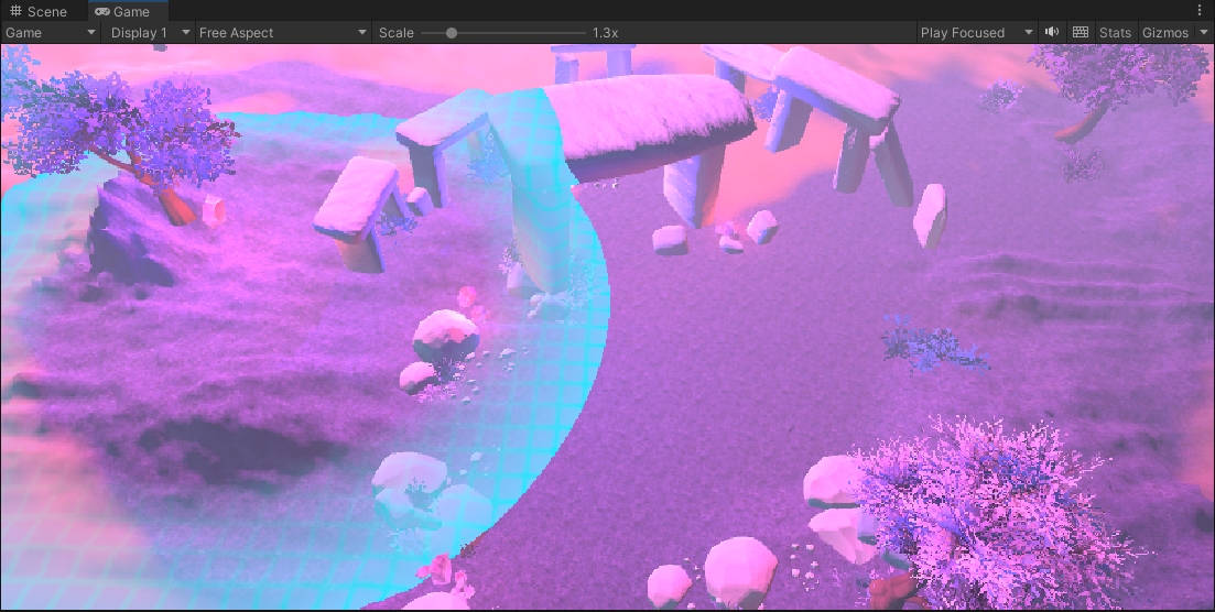
我們實現的效果是鼠標點擊某個地點之后會發射這樣一個掃描的波形。
這里就不只是一個shader可以實現的效果了,我們還需要一個C#腳本。
using System.Collections;
using System.Collections.Generic;
using UnityEngine;// 該腳本實現了一個掃描效果,當用戶點擊物體時,掃描效果會從該位置開始,并隨時間擴展
// 這個腳本會在編輯模式下也生效([ExecuteInEditMode]屬性)
[ExecuteInEditMode]
public class PosScanEffect : MonoBehaviour
{// 用于存儲掃描效果的材質(shader),此材質會控制實際的視覺效果public Material ScanMat;// 控制掃描速度,掃描的范圍會根據這個值逐漸增大public float ScanSpeed = 20;// 掃描計時器,決定掃描的進度,隨著時間的推移,掃描的范圍會增大public float scanTimer = 0;// 存儲相機組件的引用private Camera scanCam;// 記錄掃描的中心點,即鼠標點擊時的物體位置private Vector3 ScanPoint = Vector3.zero;// 初始化方法,這里沒有初始化操作void Awake(){}// 每一幀調用,主要用于計算掃描參數和更新掃描效果private void Update(){// 獲取當前物體上的相機組件scanCam = GetComponent<Camera>();// 啟用深度紋理(Depth)和法線深度紋理(DepthNormals),這些紋理對后續的渲染處理至關重要scanCam.depthTextureMode |= DepthTextureMode.Depth;scanCam.depthTextureMode |= DepthTextureMode.DepthNormals;// 獲取相機的長寬比float aspect = scanCam.aspect;// 獲取相機的遠裁剪平面(遠離相機的最大距離)float farPlaneDistance = scanCam.farClipPlane;// 根據相機的視野(field of view)計算出上方向量,用于定位視錐體的邊界Vector3 midup = Mathf.Tan(scanCam.fieldOfView / 2 * Mathf.Deg2Rad) * farPlaneDistance * scanCam.transform.up;// 計算右方向量,同樣用于確定視錐體的邊界Vector3 midright = Mathf.Tan(scanCam.fieldOfView / 2 * Mathf.Deg2Rad) * farPlaneDistance * scanCam.transform.right * aspect;// 計算遠裁剪平面的中心點位置Vector3 farPlaneMid = scanCam.transform.forward * farPlaneDistance;// 根據計算出的參數確定視錐體的四個角的世界坐標Vector3 bottomLeft = farPlaneMid - midup - midright;Vector3 bottomRight = farPlaneMid - midup + midright;Vector3 upLeft = farPlaneMid + midup - midright;Vector3 upRight = farPlaneMid + midup + midright;// 創建一個矩陣來表示視錐體的四個角Matrix4x4 frustumCorner = new Matrix4x4();frustumCorner.SetRow(0, bottomLeft); // 設置底左角frustumCorner.SetRow(1, bottomRight); // 設置底右角frustumCorner.SetRow(2, upRight); // 設置上右角frustumCorner.SetRow(3, upLeft); // 設置上左角// 將視錐體的矩陣傳遞給ShaderScanMat.SetMatrix("_FrustumCorner", frustumCorner);// 進行射線檢測,獲取鼠標點擊的世界坐標RaycastHit hit;Ray ray = Camera.main.ScreenPointToRay(Input.mousePosition); // 將鼠標屏幕坐標轉換為射線if (Input.GetMouseButton(0) && Physics.Raycast(ray, out hit)) // 如果按下左鍵并且射線與物體碰撞{scanTimer = 0; // 重置掃描計時器ScanPoint = hit.point; // 獲取碰撞點的位置作為掃描的起始點}// 增加掃描計時器,控制掃描的進度scanTimer += Time.deltaTime;// 將掃描的起始位置和掃描進度傳遞給材質(Shader)ScanMat.SetVector("_ScanCenter", ScanPoint);ScanMat.SetFloat("_ScanRange", scanTimer * ScanSpeed);// 將相機的世界坐標變換矩陣傳遞給ShaderScanMat.SetMatrix("_CamToWorld", scanCam.cameraToWorldMatrix);}// 在渲染圖像時調用,進行后處理操作,應用掃描效果private void OnRenderImage(RenderTexture source, RenderTexture destination){// 將相機的遠裁剪平面距離傳遞給材質(Shader),用于控制掃描的范圍ScanMat.SetFloat("_CamFar", GetComponent<Camera>().farClipPlane);// 使用Graphics.Blit方法將源紋理渲染到目標紋理,并應用掃描效果的材質Graphics.Blit(source, destination, ScanMat);}
}
具體的代碼作用注釋里已經寫明了。
我們重點還是來看看著色器的寫法:
Shader "Chapter2/PointScanShader"
{Properties{// 主要紋理,用于物體表面的紋理_MainTex ("Texture", 2D) = "white" {}// 掃描紋理,用于顯示掃描的圖像或效果_ScanTex("ScanTexure", 2D) = "white" {}// 掃描的范圍,控制掃描從中心開始的距離_ScanRange("ScanRange", float) = 0// 掃描寬度,控制掃描的寬度,影響掃描的可見區域_ScanWidth("ScanWidth", float) = 0// 掃描的背景顏色_ScanBgColor("ScanBgColor", color) = (1, 1, 1, 1)// 掃描時網格的顏色_ScanMeshColor("ScanMeshColor", color) = (1, 1, 1, 1)// 網格線的寬度_MeshLineWidth("MeshLineWidth", float) = 0.3// 網格的寬度,用于控制網格分割的尺寸_MeshWidth("MeshWidth", float) = 1// 縫隙的平滑度,控制縫隙的過渡效果_Smoothness("SeamBlending", Range(0, 0.5)) = 0.25}SubShader{// 不使用背面剔除(Cull Off),不寫入深度緩存(ZWrite Off),且始終通過深度測試(ZTest Always)//Cull Off ZWrite Off ZTest AlwaysPass{CGPROGRAM#pragma vertex vert#pragma fragment frag// 引用Unity的內置CG代碼庫#include "UnityCG.cginc"// 定義頂點著色器的數據結構struct appdata{float4 vertex : POSITION; // 頂點位置float2 uv : TEXCOORD0; // 頂點紋理坐標};// 定義片段著色器的數據結構struct v2f{float2 uv : TEXCOORD0; // 傳遞給片段著色器的紋理坐標float2 uv_depth : TEXCOORD1; // 用于傳遞深度信息的紋理坐標float4 interpolatedRay : TEXCOORD2; // 傳遞與掃描效果相關的視錐體數據float4 vertex : SV_POSITION; // 頂點最終位置};// 定義一個矩陣,用于描述視錐體四個角的坐標float4x4 _FrustumCorner;// 頂點著色器:計算頂點的最終位置,并計算視錐體四個角的插值數據v2f vert(appdata v){v2f o;o.vertex = UnityObjectToClipPos(v.vertex); // 計算頂點的最終位置o.uv = v.uv; // 將紋理坐標傳遞給片段著色器o.uv_depth = v.uv; // 將紋理坐標傳遞給深度計算// 根據UV坐標的不同區域選擇不同的視錐體角int rayIndex;if (v.uv.x < 0.5 && v.uv.y < 0.5){rayIndex = 0;}else if (v.uv.x > 0.5 && v.uv.y < 0.5){rayIndex = 1;}else if (v.uv.x > 0.5 && v.uv.y > 0.5){rayIndex = 2;}else{rayIndex = 3;}// 從視錐體四個角中選擇一個,傳遞給片段著色器o.interpolatedRay = _FrustumCorner[rayIndex];return o;}// 聲明材質參數,允許外部設置sampler2D _MainTex;sampler2D _ScanTex;float _ScanRange;float _ScanWidth;float3 _ScanCenter;fixed4 _ScanBgColor;fixed4 _ScanMeshColor;float _MeshLineWidth;float _MeshWidth;float4x4 _CamToWorld;fixed _Smoothness;// 聲明用于獲取深度信息的紋理sampler2D_float _CameraDepthTexture;sampler2D _CameraDepthNormalsTexture;// 片段著色器:計算像素的最終顏色fixed4 frag(v2f i) : SV_Target{float tempDepth;half3 normal;  // 獲取該像素的法線和深度值DecodeDepthNormal(tex2D(_CameraDepthNormalsTexture, i.uv), tempDepth, normal);// 將法線從相機空間轉換到世界空間normal = mul((float3x3)_CamToWorld, normal);normal = normalize(max(0, (abs(normal) - _Smoothness)));  // 對法線進行平滑處理// 獲取該像素的顏色fixed4 col = tex2D(_MainTex, i.uv);// 通過深度紋理獲取該像素的深度值,并轉換為線性深度float depth = SAMPLE_DEPTH_TEXTURE(_CameraDepthTexture, i.uv_depth);float linearDepth = Linear01Depth(depth);// 計算該像素在世界空間中的位置float3 pixelWorldPos = _WorldSpaceCameraPos + linearDepth * i.interpolatedRay;// 計算像素到掃描中心的距離float pixelDistance = distance(pixelWorldPos, _ScanCenter);// 計算該像素的方向向量float3 pixelDir = pixelWorldPos - _ScanCenter;// 使用網格寬度將像素位置進行取模操作,用于創建網格效果float3 modulo = pixelWorldPos - _MeshWidth * floor(pixelWorldPos / _MeshWidth);modulo = modulo / _MeshWidth;// 使用平滑插值創建網格線效果float3 meshCol = smoothstep(_MeshLineWidth, 0, modulo) + smoothstep(1 - _MeshLineWidth, 1, modulo);// 將掃描背景顏色和網格顏色進行插值fixed4 scanMeshCol = lerp(_ScanBgColor, _ScanMeshColor, saturate(dot(meshCol, 1 - normal)));// 如果像素距離掃描中心在指定范圍內,執行掃描效果if (_ScanRange - pixelDistance > 0 && _ScanRange - pixelDistance < _ScanWidth && linearDepth < 1){// 根據像素距離計算掃描百分比fixed scanPercent = 1 - (_ScanRange - pixelDistance) / _ScanWidth;// 通過插值將當前顏色與網格顏色混合,生成掃描效果col = lerp(col, scanMeshCol, scanPercent);}// 返回最終顏色return col;}ENDCG}}
}
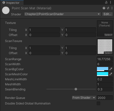
Properties{// 主要紋理,用于物體表面的紋理_MainTex ("Texture", 2D) = "white" {}// 掃描紋理,用于顯示掃描的圖像或效果_ScanTex("ScanTexure", 2D) = "white" {}// 掃描的范圍,控制掃描從中心開始的距離_ScanRange("ScanRange", float) = 0// 掃描寬度,控制掃描的寬度,影響掃描的可見區域_ScanWidth("ScanWidth", float) = 0// 掃描的背景顏色_ScanBgColor("ScanBgColor", color) = (1, 1, 1, 1)// 掃描時網格的顏色_ScanMeshColor("ScanMeshColor", color) = (1, 1, 1, 1)// 網格線的寬度_MeshLineWidth("MeshLineWidth", float) = 0.3// 網格的寬度,用于控制網格分割的尺寸_MeshWidth("MeshWidth", float) = 1// 縫隙的平滑度,控制縫隙的過渡效果_Smoothness("SeamBlending", Range(0, 0.5)) = 0.25一些主要的屬性,含義已在注釋中寫明。
// 定義片段著色器的數據結構struct v2f{float2 uv : TEXCOORD0; // 傳遞給片段著色器的紋理坐標float2 uv_depth : TEXCOORD1; // 用于傳遞深度信息的紋理坐標float4 interpolatedRay : TEXCOORD2; // 傳遞與掃描效果相關的視錐體數據float4 vertex : SV_POSITION; // 頂點最終位置};頂點著色器的輸出以及片元著色器的輸入中除了uv坐標和頂點坐標以外還有一個傳遞深度信息的uv坐標以及一個與掃描效果相關的變量。
// 定義一個矩陣,用于描述視錐體四個角的坐標float4x4 _FrustumCorner;注意這里定義矩陣的方式:float4*4,這個矩陣用來描述視錐體的四個角。
// 頂點著色器:計算頂點的最終位置,并計算視錐體四個角的插值數據v2f vert(appdata v){v2f o;o.vertex = UnityObjectToClipPos(v.vertex); // 計算頂點的最終位置o.uv = v.uv; // 將紋理坐標傳遞給片段著色器o.uv_depth = v.uv; // 將紋理坐標傳遞給深度計算// 根據UV坐標的不同區域選擇不同的視錐體角int rayIndex;if (v.uv.x < 0.5 && v.uv.y < 0.5){rayIndex = 0;}else if (v.uv.x > 0.5 && v.uv.y < 0.5){rayIndex = 1;}else if (v.uv.x > 0.5 && v.uv.y > 0.5){rayIndex = 2;}else{rayIndex = 3;}// 從視錐體四個角中選擇一個,傳遞給片段著色器o.interpolatedRay = _FrustumCorner[rayIndex];return o;}我們根據不同的視錐體的位置來給定一個序號,從這四個序號中選擇一個傳給片元著色器。
// 片段著色器:計算像素的最終顏色
fixed4 frag(v2f i) : SV_Target
{float tempDepth;half3 normal;  // 獲取該像素的法線和深度值DecodeDepthNormal(tex2D(_CameraDepthNormalsTexture, i.uv), tempDepth, normal);// 將法線從相機空間轉換到世界空間normal = mul((float3x3)_CamToWorld, normal);normal = normalize(max(0, (abs(normal) - _Smoothness)));  // 對法線進行平滑處理// 獲取該像素的顏色fixed4 col = tex2D(_MainTex, i.uv);// 通過深度紋理獲取該像素的深度值,并轉換為線性深度float depth = SAMPLE_DEPTH_TEXTURE(_CameraDepthTexture, i.uv_depth);float linearDepth = Linear01Depth(depth);// 計算該像素在世界空間中的位置float3 pixelWorldPos = _WorldSpaceCameraPos + linearDepth * i.interpolatedRay;// 計算像素到掃描中心的距離float pixelDistance = distance(pixelWorldPos, _ScanCenter);// 計算該像素的方向向量float3 pixelDir = pixelWorldPos - _ScanCenter;// 使用網格寬度將像素位置進行取模操作,用于創建網格效果float3 modulo = pixelWorldPos - _MeshWidth * floor(pixelWorldPos / _MeshWidth);modulo = modulo / _MeshWidth;// 使用平滑插值創建網格線效果float3 meshCol = smoothstep(_MeshLineWidth, 0, modulo) + smoothstep(1 - _MeshLineWidth, 1, modulo);// 將掃描背景顏色和網格顏色進行插值fixed4 scanMeshCol = lerp(_ScanBgColor, _ScanMeshColor, saturate(dot(meshCol, 1 - normal)));// 如果像素距離掃描中心在指定范圍內,執行掃描效果if (_ScanRange - pixelDistance > 0 && _ScanRange - pixelDistance < _ScanWidth && linearDepth < 1){// 根據像素距離計算掃描百分比fixed scanPercent = 1 - (_ScanRange - pixelDistance) / _ScanWidth;// 通過插值將當前顏色與網格顏色混合,生成掃描效果col = lerp(col, scanMeshCol, scanPercent);}// 返回最終顏色return col;
}
首先我們使用DecodeDepthNormal函數從_CameraDepthNormalsTexture中獲取到法線和深度值,然后將法線經過一系列處理轉換到世界空間。我們將深度值轉換成線性深度之后用來計算該像素在世界空間的位置與掃描中心的距離,同時計算這個像素到掃描中心的向量。因為我們要實現網格效果,網格效果是一格一格實現的,所以我們需要將像素的位置取模來確定具體在第幾個網格,然后將背景的顏色和網格顏色進行插值實現混合的效果,最終返回顏色。
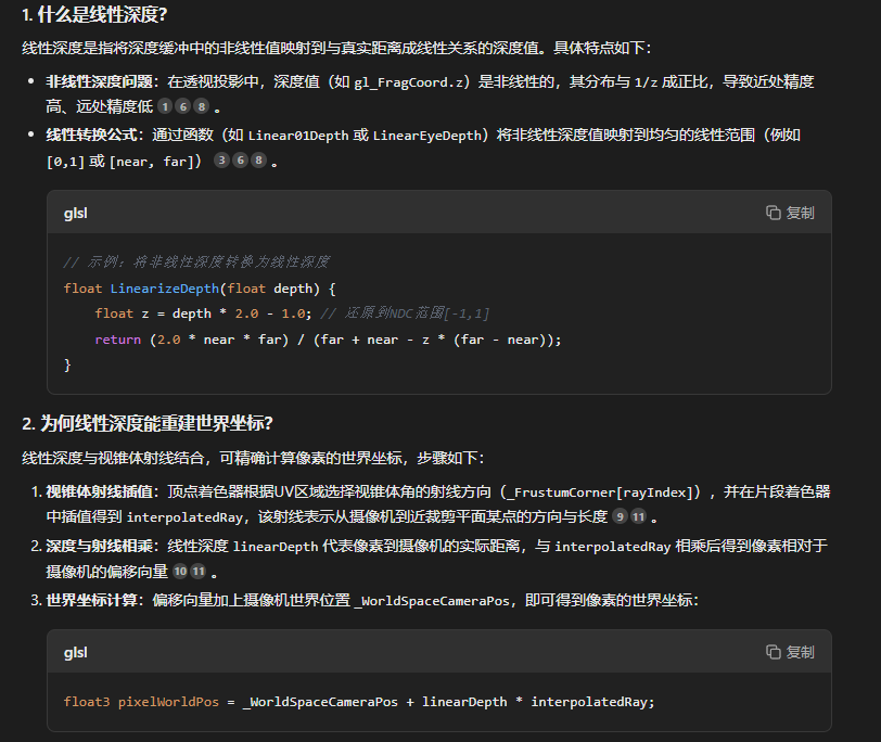
關于線性深度:


)
)
:復雜地形精講之臺階)

)


模塊代碼解析與流程梳理)
