寄存器和pin
In these years the LCD is finding widespread use. It has replaced the LEDs or other multi-segment LEDs.This is due to the following reasons:
近年來, LCD正在廣泛使用。 它已替換LED或其他多段LED,原因如下:
The declining price of LCDs.
液晶顯示器價格下降。
The ability to display numbers, characters and graphics. This is in contrast to LEDs which are limited to numbers and a few characters.
顯示數字,字符和圖形的能力。 這與限于數字和幾個字符的LED形成對比。
Ease of programming of character and graphics.
易于對字符和圖形進行編程。
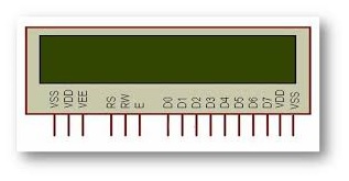
Image source: http://electronica4u.blogspot.com/2012/03/how-16x2-alphanumeric-lcd-works.html
圖片來源:http://electronica4u.blogspot.com/2012/03/how-16x2-alphanumeric-lcd-works.html
Image source: http://jinghanda.manufacturer.globalsources.com/si/6008801429542/pdtl/Alphanumeric-LCD/1035064002/Alphanumeric-LCD-Module.htm
圖片來源:http://jinghanda.manufacturer.globalsources.com/si/6008801429542/pdtl/Alphanumeric-LCD/1035064002/Alphanumeric-LCD-Module.htm
LCD密碼 (LCD PINs)
The LCD that we are discussing here in this section has 14 pins. The function of each Pin is given below:
我們在本節中討論的LCD有14個引腳。 每個引腳的功能如下:
V cc ,V ss和V EE (Vcc, Vss and VEE)
Vcc and Vss provide +5V and ground to our LCD, respectively, VEE is used for controlling LCD contrast i.e. dimming the brightness or increasing the brightness of LCD.
V cc和V ss分別為我們的LCD提供+ 5V和接地,V EE用于控制LCD對比度,即調暗亮度或增加LCD的亮度。
RS(寄存器選擇) (RS (Register Select))
There are two very important registers inside the LCD. The RS pin is used for the selection of these registers. If RS=0, the instruction command code register is selected, which allows the user to send commands for the LCD such as clear display, cursor at home, and so on. If RS=1, the data register is selected. It allows the user to send data that is to be displayed on the LCD.
LCD內部有兩個非常重要的寄存器。 RS引腳用于選擇這些寄存器。 如果RS = 0 ,則選擇指令命令代碼寄存器,從而允許用戶向LCD發送命令,例如清晰顯示,光標在家等。 如果RS = 1 ,則選擇數據寄存器。 它允許用戶發送要在LCD上顯示的數據。
讀/寫(R / W) (R/W (Read/Write))
R/W inputs allows the user to write information to the LCD or read information from it. R/W is set 0 while reading and R/W is set 1 when writing.
R / W輸入允許用戶將信息寫入LCD或從LCD讀取信息。 讀時R / W設置為0 ,寫時R / W設置為1 。
E(啟用) (E (Enable))
The enable pin is used by the LCD to latch information presented to its data pins.
LCD使用使能引腳來鎖存提供給其數據引腳的信息。
When data is supplied to the data pins, a high-to-low pulse must be applied to this pin in order for the LCD to latch in the data present at the data pins. This pulse must be a minimum of 450ns wide.
當數據提供給數據引腳時,必須向該引腳施加一個高到低脈沖,以便LCD鎖存數據引腳上的數據。 此脈沖的寬度必須至少為450ns 。
D0-D7 (D0-D7)
The 8-bit datapins, D0-D7 are used to send information to the LCD or read the contents of the LCD’s internal Registers. We send the ASCII codes is sent to the LCD to display numbers and letters for the letter A-Z, a-z, and numbers 0-9 to these pins while masking RS=1.
8位數據引腳D0-D7用于將信息發送到LCD或讀取LCD內部寄存器的內容。 我們將ASCII碼發送到LCD,以在屏蔽RS = 1的同時向這些引腳顯示字母AZ,az和數字0-9的數字和字母。
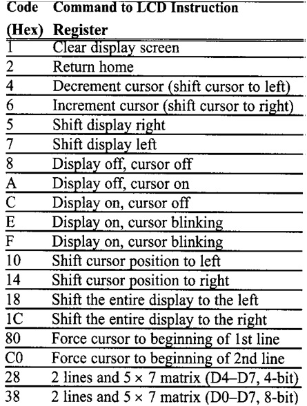
There are also instruction command codes that can be sent to the LCD to clear the display or force the cursor to the home position or blink the cursor.
也可以將指令命令代碼發送到LCD,以清除顯示內容或將光標強制到起始位置或使光標閃爍。
The next table here incudes all the instruction command codes. To interface LCD to the AVR we can use 4-bit mode and 8-bit mode. The 8-bit data interfacing is easier to program but uses 4 more pins.
下表中包含所有指令命令代碼。 要將LCD連接到AVR,我們可以使用4位模式和8位模式。 8位數據接口更易于編程,但又使用了4個引腳。
翻譯自: https://www.includehelp.com/embedded-system/pin-diagram-and-registers-of-16x2-lcd.aspx
寄存器和pin

)
:深拷貝與淺拷貝(Deep Copy and Shallow Copy))


)
方法與示例)


方法及示例)


方法與示例)
